Artisan IB Range Hood Hotte Installation Instructions Use and Care Guide Instructions d’installation Mode d’emploi et d’entretien FBI 362 XS IB FBI 482 XS IB
INDEX WARNINGS AND REQUIREMENTS .....................................................................................................................................3 RECOMMENDATIONS AND SUGGESTIONS ......................................................................................................................6 DIMENSIONS and MAIN PARTS...........................................................................................................................................7 INSTALLATION ..............
READ AND SAVE THESE INSTRUCTIONS The Installer must leave these instructions with the homeowner. The homeowner must keep these instructions for future reference and for local electrical inspectors’ use. READ THESE INSTRUCTIONS BEFORE YOU START INSTALLING THIS RANGEHOOD WARNING: - TO REDUCE THE RISK OF A RANGE TOP GREASE FIRE: Never leave surface units unattended at high settings. Boilovers cause smoking and greasy spillovers that may ignite. Heat oils slowly on low or medium setting.
WARNING • • • • • • Venting system MUST terminate outside the home. DO NOT terminate the ductwork in an attic or other enclosed space. DO NOT use 4" laundry-type wall caps. Flexible-type ductwork is NOT recommended. DO NOT obstruct the flow of combustion and ventilation air. Failure to follow venting requirements may result in a fire. ELECTRICAL REQUIREMENTS A 120 volt, 60 Hz AC-only electrical supply is required on a separate 15 amp fused circuit. A timedelay fuse or circuit breaker is recommended.
WARNING - TO REDUCE THE RISK OF FIRE, ELECTRICAL SHOCK, OR INJURY TO PERSONS, OBSERVE THE FOLLOWING: Installation Work And Electrical Wiring Must Be Done By Qualified Person(s) In Accordance With All Applicable Codes And Standards, Including Fire-Rated Construction. Sufficient air is needed for proper combustion and exhausting of gases through the flue (chimney) of fuel burning equipment to prevent backdrafting.
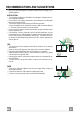
RECOMMENDATIONS AND SUGGESTIONS The Instructions for Use apply to several versions of this appliance. Accordingly, you may find descriptions of individual features that do not apply to your specific appliance. INSTALLATION • The manufacturer will not be held liable for any damages resulting from incorrect or improper installation. • Check that the main voltage corresponds to that indicated on the rating plate fixed to the inside of the hood.
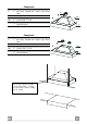
DIMENSIONS and MAIN PARTS Dimensions EN 7 7
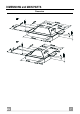
Components Ref. 1 10 Ref. 12a Q.ty Product Components 1 Hood Body, complete with: Controls, Light, Blower, Filters 1 Damper Q.ty Installation Components 4 Screws M3/16” x 1 “ 9/16 Q.ty Documentation 1 Instruction Manual 10 12a 1 Components Ref. 1 10 Ref. 12a Q.ty Product Components 1 Hood Body, complete with: Controls, Light, Blower, Filters 2 Damper Q.ty Installation Components 4 Screws M3/16” x 1 “ 9/16 Q.
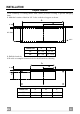
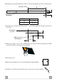
INSTALLATION Prepare Location Cover countertop or cooking surface with a thick, protective covering to prevent damaging them. 1. Mark the locations of the four 1/4 " holes on the hood support as shown. A B 2" 3/4 17" 5/16 1/4 " HOOD size A B 36" 31" 7/16 15" 3/4 43" 7/16 21" 11/16 48" 2. Drill the four holes. 3. Provide a rectangular clearance hole for the blower motor housing.
4.If using the rear electrical knockout, drill a 1”1/4 hole through the wall at the location shown. Centerline of hood A 2” Hood support (front view) HOOD size A 36” 14” 3/16 48” 20” 1/4 5. If using the top electrical knockout, drill a 1“ 1/4 hole through the hood support at the location shown. Hood support (top view) 2” Right rear hood mounting hole 1”1/2 6. Remove the filters one at a time holding them up with one hand and pulling the handle downwards with the other hand at the same time. 7.
ELECTRICAL CONNECTION • Remove the cover from the Field Wiring Compartment with a phillips screwdriver. • Feed the Power Supply Cable through the electrical knockout. Connect the Power Supply Cable to the range- hood cable. Attach the Power Supply Cable grounding lead to the green screw provided. Attach the White lead of the power supply to the White lead of the rangehood with a twist-on type wire connector.
USE 3 1 2 0 1 0 1 V L M Control board L Light Switches the lighting system on and off M Motor Switches the extractor motor on and off V Speed Sets the operating speed of the extractor: 1. Low speed, used for a continuous and silent air change in the presence of light cooking vapour. 2. Medium speed, suitable for most operating conditions given the optimum treated air flow/noise level ratio. 3. Maximum speed, used for eliminating the highest cooking vapour emission, including long periods.
CARE Grease filters CLEANING METAL SELF- SUPPORTING GREASE FILTERS • The filters must be cleaned every 2 months of operation, or more frequently for particularly heavy usage, and can be washed in a dishwasher. • Remove the filters one at a time holding them up with one hand and pulling the handle downwards with the other hand at the same time. • Wash the filters, taking care not to bend them. Allow them to dry before refitting.
TABLE DES MATIÈRES AVERTISSEMENT ET CONDITIONS N ÉCESSAIRES ......................................................................................................15 CONSEILS ET SUGGESTIONS ..........................................................................................................................................18 DIMENSIONS et PRINCIPALES PIÈCES............................................................................................................................19 INSTALLATION ..........
LIRE ET CONSERVER CES INSTRUCTIONS L’installateur doit laisser ces instructions au propriétaire. Le propriétaire doit conserver ces instructions en vue d’une utilisation subséquente et pour le bénéfice de l’inspecteur en électricité.
AVERTISSEMENT • • • • • • Le système d’évacuation DOIT se terminer à l’extérieur. N’ÉVACUEZ PAS le conduit dans un grenier ou dans tout autre espace fermé. N’UTILISEZ PAS un clapet de sécheuse à 4 pouces. ON DÉCONSEILLE l’emploi de conduit d’évacuation flexible. N’ENCOMBREZ PAS la circulation d’air. Le fait de ne pas respecter ces avertissements pourrait occasionner un incendie.
AVERTISSEMENT – POUR MINIMISER LES RISQUES D’INCENDIE, CHOC ÉLECTRIQUES OU BLESSURES, OBSERVER CETTE RÈGLE : l’installation et le raccordement électrique ne doivent être effectués que par un technicien(s) qualifié, selon tous les codes municipaux. Afin d’obtenir un rendement maximal en ce qui a trait à la combustion ainsi qu’à l’évacuation des gaz par la conduite de cheminée et pour qu’il n’y ait pas de reflux des gaz de combustion, une bonne aération est nécessaire pour tous les appareils à combustion.
CONSEILS ET SUGGESTIONS Les instructions d’utilisation s’applique à plusieurs versions de ce type d’appareil. En conséquence, il est possible que vous trouviez des descriptions de caractéristiques ne s'appliquant pas à votre appareil. INSTALLATION • Le fabricant décline toute responsabilité en cas de dommage dû à une installation inadéquate ou non conforme aux règles de l’art. • Vérifiez que la tension du secteur correspond à la valeur qui figure sur la plaquette apposée à l’intérieur de la hotte.
DIMENSIONS et PRINCIPALES PIÈCES Dimensions FR 1 19 9
Composantes Réf. 1 10 Réf. 12a Qté Pièces du produit 1 Corps de la hotte équipé de : commandes, lumière, groupe ventilateur, filtres 1 Clapet d’air Qté Pièces servant à l’installation 4 Vis M3/16” x 1 “ 9/16 Qté Documentation 1 Manuel d’instructions 10 12a 1 Composantes Réf. 1 10 Réf.
INSTALLATION Préparation de la surface de travail Recouvrir le comptoir ou le dessus de la cuisinière avec une protection assez épaisse afin d’éviter de les endommager. 1. Indiquer l’endroit où effectuer les quatre trous de 1/4 " sur le support de la hotte. A B 2" 3/4 17" 5/16 1/4 " Hotte A B 36" 31" 7/16 15" 3/4 48" 43" 7/16 21" 11/16 2. Percer les quatre trous. 3. Laisser un trou de passage rectangulaire pour la boîte du moteur souffleur.
4. Si l’entrée électrique sectionnable arrière est utilisée, percer un trou de 1”1/4 à travers le mur à l’emplacement indiqué. Médiane de la hotte A 2” Support de la hotte (vue de face) Hotte A 36” 14” 3/16 48” 20” 1/4 5. Si l’entrée électrique sectionnable du haut est utilisée, percer un trou de 1”1/4 à travers le mur à l’emplacement indiqué. Support de la hotte (vue en plongée) 2” Trou de montage droit à l’arrière de la hotte 1”1/2 6. Retirer les filtres.
BRANCHEMENT ÉLECTRIQUE • Retirer le couvercle du compartiment de filage à l’aide d’un tournevis Phillips. • Passer le câble d’alimentation dans la pastille enfonçable. Brancher le câble d’alimentation sur la hotte. Attacher le conducteur de mise à la terre du câble d’alimentation à la vis verte fournie. Attacher le fil blanc du câble d’alimentation au fil blanc de la hotte avec une cosse (connecteur de fils).
UTILISATION 3 1 2 0 1 0 1 V L M Tableaux des commandes L Lumières Allume et éteint l’éclairage. M Moteur Allume et éteint le moteur aspiration V Vitesses Détermine les vitesses d’exploitation ainsi subdivisées: 1.Vitesse minimale, pour un rechange d’air permanent particulièrement silencieux en cas de faibles vapeurs de cuisson. 2.Vitesse moyenne pour la plupart des conditions d’utilisation, étant donné le rapport optimal entre débit d’air traité et niveau sonore. 3.
CARE Filtres anti-graisse NETTOYAGE FILTRES ANTI-GRAISSE METALLIQUES AUTOPORTEURS • Lavables au lave-vaisselle, ils doivent être lavés environ tous les 2 mois d’emploi ou plus fréquemment en cas d’emploi particulièrement intense. • Enlevez les filtres l’un après l’autre en les soutenant avec une main et en tirant en même temps la poignée vers le bas avec l’autre main. • Laver les filtres en évitant de les plier et les laisser sécher avant de les remonter.
436003867_01 - 070605