IT Istruzioni per l’uso e l’installazione Cappa GB Instructions for use and installation FR Mode d’emploi et installation DE Bedienungsanleitung und Einrichtung TR Kullanım ve montaj talimatları Cooker Hood Hotte de Cuisine Dunstabzugshaube Davlumbaz FCH 906
Libretto di Istruzioni INDICE CONSIGLI E SUGGERIMENTI.............................................................................................................................................. 7 CARATTERISTICHE.............................................................................................................................................................. 8 INSTALLAZIONE.............................................................................................................................
Instructions Manual INDEX RECOMMENDATIONS AND SUGGESTIONS....................................................................................................................14 CHARACTERISTICS............................................................................................................................................................15 INSTALLATION .....................................................................................................................................................
Manuel d’Instructions SOMMAIRE CONSEILS ET SUGGESTIONS ..........................................................................................................................................21 CARACTERISTIQUES.........................................................................................................................................................22 INSTALLATION ...................................................................................................................................
Bedienungsanleitung INHALTSVERZEICHNIS EMPFEHLUNGEN UND HINWEISE....................................................................................................................................28 CHARAKTERISTIKEN .........................................................................................................................................................29 MONTAGE.....................................................................................................................................
Kullanim Kilavuku IÇERIKLER TAVSIYELER VE ÖNERILER..............................................................................................................................................35 ÖZELLIKLER........................................................................................................................................................................36 MONTAJ..................................................................................................................................
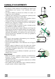
CONSIGLI E SUGGERIMENTI INSTALLAZIONE • Il produttore declina qualsiasi responsabilità per danni dovuti ad installazione non corretta o non conforme alle regole dell’arte. • La distanza minima di sicurezza tra il Piano di cottura e la Cappa deve essere di 650 mm. • Verificare che la tensione di rete corrisponda a quella riportata nella targhetta posta all’interno della Cappa. • Per Apparecchi in Classe Ia accertarsi che l’impianto elettrico domestico garantisca un corretto scarico a terra.
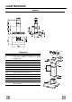
CARATTERISTICHE Ingombro 15 14.1 Componenti Q.tà Componenti di Prodotto 1 Corpo Cappa completo di: Comandi, Luce, Gruppo Ventilatore, Filtri 2 1 Camino Telescopico formato da: 2.1 1 Camino Superiore 2.2 1 Camino Inferiore 9 1 Flangia di Riduzione ø 150-120 mm 14.1 2 Prolunga Raccordo Uscita Aria 15 1 Raccordo Uscita Aria Rif. Q.tà Componenti di Installazione 7.2.1 2 Staffe Fissaggio Camino Superiore 7.3 1 Staffa Sostegno Raccordo 11 6 Tasselli 12a 6 Viti 4,2 x 44,4 12c 6 Viti 2,9 x 9,5 Q.
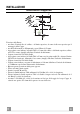
INSTALLAZIONE 1÷2 Foratura Parete e Fissaggio Staffe 116 116 650 min. 400 11 12a X 7.2.1 Tracciare sulla Parete: • una linea Verticale fino al soffitto o al limite superiore, al centro della zona prevista per il montaggio della Cappa; • una linea Orizzontale a: 650 mm min. sopra il Piano di Cottura. • Appoggiare come indicato la Staffa 7.2.1 a 1-2 mm dal soffitto o dal limite superiore, allineando il suo centro (intagli) sulla linea Verticale di riferimento. • Segnare i centri dei Fori della Staffa.
Montaggio Corpo Cappa Vr • Prima di agganciare il Corpo Cappa, serrare le 2 Viti Vr situate sui punti di aggancio del Corpo Cappa. • Agganciare il Corpo Cappa alle Viti 12a. • Serrare definitivamente le Viti 12a di supporto. • Agire sulle Viti Vr per livellare il Corpo Cappa.
CONNESSIONE ELETTRICA • Collegare la Cappa all’Alimentazione di Rete interponendo un Interruttore bipolare con apertura dei contatti di almeno 3 mm. • Rimuovere i Filtri antigrasso (vedi par. “Manutenzione”) e assicurarsi che il connettore del Cavo di alimentazione sia correttamente inserito nella presa dell’Aspiratore Montaggio Camino Camino superiore • Allargare leggermente le due falde laterali, agganciarle dietro le Staffe 7.2.1 e richiuderle fino a battuta.
USO T1 T2 T4 T3 T5 L Quadro Comandi T1 TASTO ON/OFF Motore T2 T3 T4 Velocità Velocità + Velocità intensiva T5 Delay L Luci IT FUNZIONI Attiva e arresta il motore d’aspirazione. Sul display viene visualizzato lo step di velocità precedentemente impostata. Decrementa la velocità del motore: V3 →V2 → V1 Incrementa la velocità del motore: V1→V2→ V3 Attiva la velocità intensiva da qualsiasi velocità o da motore spento.Per disinserirla basta premere di nuovo lo stesso tasto o spegnere il motore.
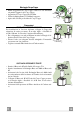
MANUTENZIONE Filtri antigrasso PULIZIA FILTRI ANTIGRASSO METALLICI AUTOPORTANTI • Sono lavabili anche in lavastoviglie, e necessitano di essere lavati ogni 2 mesi circa di utilizzo o più frequentemente, per un uso particolarmente intenso. • Togliere i Filtri uno alla volta, spingendoli verso la parte posteriore del gruppo e tirando contemporaneamente verso il basso. • Lavare i Filtri evitando di piegarli, e lasciarli asciugare prima di rimontarli.
RECOMMENDATIONS AND SUGGESTIONS INSTALLATION • The manufacturer will not be held liable for any damages resulting from incorrect or improper installation. • The minimum safety distance between the cooker top and the extractor hood is 650 mm. • Check that the mains voltage corresponds to that indicated on the rating plate fixed to the inside of the hood. • For Class I appliances, check that the domestic power supply guarantees adequate earthing.
CHARACTERISTICS Dimensions 15 14.1 Components Q.ty Product Components 1 Hood Body, complete with: Controls, Light, Blower, Filters 2 1 Telescopic Chimney comprising: 2.1 1 Upper Section 2.2 1 Lower Section 9 1 Reducer Flange ø 150-120 mm 14.1 2 Air Outlet Connection Extension 15 1 Air Outlet Connection Ref. Q.ty Installation Components 7.2.1 2 Upper Chimney Section Fixing Brackets 7.3 1 Air Outlet Connection Support 11 6 Wall Plugs 12a 6 Screws 4,2 x 44,4 12c 6 Screws 2,9 x 9,5 Q.
INSTALLATION 1÷2 Wall drilling and bracket fixing 116 116 650 min. 400 11 12a X 7.2.1 Wall marking: • Draw a vertical line on the supporting wall up to the ceiling, or as high as practical, at the centre of the area in which the hood will be installed. • Draw a horizontal line at 650 mm above the hob. • Place bracket 7.2.1 on the wall as shown about 1-2 mm from the ceiling or upper limit aligning the centre (notch) with the vertical reference line.
Mounting the hood body Vr • Before attaching the hood body, tighten the two screws Vr located on the hood body mounting points. • Hook the hood body onto the screws 12a. • Fully tighten support screws 12a. • Adjust screws Vr to level the hood body. 12a Connections DUCTED VERSION AIR EXHAUST SYSTEM When installing the ducted version, connect the hood to the chimney using either a flexible or rigid pipe ø 150 or 120 mm, the choice of which is left to the installer.
ELECTRICAL CONNECTION • Connect the hood to the mains through a two-pole switch having a contact gap of at least 3 mm. • Remove the grease filters (see paragraph Maintenance) being sure that the connector of the feeding cable is correctly inserted in the socket placed on the side of the fan. Flue assembly Upper exhaust flue • Slightly widen the two sides of the upper flue and hook them behind the brackets 7.2.1, making sure that they are well seated.
USE T1 T2 T4 T3 T5 L Control panel TOUCH CONTROL T1 ON/OFF Motor T2 T3 T4 Speed Speed + Intensive speed T5 Delay L Lighting EN FUNCTION Switches the hood motor on and off. The latest selected speed appears on the display. Decreases the suction speed: V3 → V2 → V1 Increases the suction speed: V1 → V2 → V3 Activates the intensive speed from any previously selected speed. The intensive speed can be activated even when the motor is OFF.
MAINTENANCE Grease filters CLEANING METAL SELF- SUPPORTING GREASE FILTERS • The filters must be cleaned every 2 months of operation, or more frequently for particularly heavy usage, and can be washed in a dishwasher. • Remove the filters one at a time by pushing them towards the back of the group and pulling down at the same time. • Wash the filters, taking care not to bend them. Allow them to dry before refitting. • When refitting the filters, make sure that the handle is visible on the outside.
CONSEILS ET SUGGESTIONS INSTALLATION • Le fabricant décline toute responsabilité en cas de dommage dû à une installation non correcte ou non conforme aux règles de l’art. • La distance minimale de sécurité entre le plan de cuisson et la hotte doit être de 650 mm au moins. • Vérifier que la tension du secteur correspond à la valeur qui figure sur la plaquette apposée à l’intérieur de la hotte.
CARACTERISTIQUES Encombrement 15 14.1 Composants Q.té Composants de Produit 1 Corps Hotte équipé de:Comandes, Lumière,Groupe Ventilateur,Filtres 2 1 Cheminée Télescopique formée de : 2.1 1 Cheminée Supérieure 2.2 1 Cheminée Inférieure 9 1 Flasque de Réduction ø 150-120 mm 14.1 2 Rallonge Raccord Sortie Air 15 1 Raccord Sortie Air Réf. Q.té Composants pour l ’installation 7.2.1 2 Brides Fixation Cheminée Supérieure 7.3 1 Bride Support Raccord 11 6 Chevilles 12a 6 Vis 4,2 x 44,4 12c 6 Vis 2,9 x 9,5 Q.
INSTALLATION 1÷2 Perçage Paroi et Fixation Brides 116 116 650 min. 400 11 12a X 7.2.1 Tracer sur la paroi: • une ligne verticale allant jusqu’au plafond ou à la limite supérieure, au centre de la zone prévue pour le montage de la hotte; • une ligne horizontale à 650 mm min. au-dessus du plan de cuisson. • Poser comme indiqué une bride 7.2.1 sur la paroi à 1-2 mm du plafond ou de la limite supérieure, en alignant son centre (découpes) sur la ligne verticale de repère.
Vr Montage Corps Hotte • Avant d’accrocher le corps hotte, serrer les deux vis Vr situées sur les points d’accrochage du corps hotte. • Accrocher le corps hotte aux vis 12a prévues à cet effet. • Serrer définitivement les vis 12a de support. • Agir sur les vis Vr pour niveler le corps hotte. 12a Branchements SORTIE AIR VERSION ASPIRANTE En cas d’installation en version aspirante, brancher la hotte à la tuyauterie de sortie via un tube ri-gide ou flexible de ø 150 ou 120 mm, au choix de l’installateur.
BRANCHEMENT ELECTRIQUE • Brancher la hotte sur le secteur en interposant un interrupteur bipolaire avec ouverture des contacts d’au moins 3 mm. • Enlever les filtres à graisse (voir § "Entretien") et s'assurer que le connecteur du câble d'alimentation soit bien branché dans la prise du diffuseur. Montage Cheminée Cheminée supérieure • Elargir légèrement les deux bords latériaux, et les accrocher derrières les brides 7.2.1 ; refermer jusqu’à la butée.
UTILISATION T1 T2 T3 T4 T5 L Tableau des commandes T1 TOUCHE ON/OFF Moteur T2 T3 T4 Vitesse Vitesse + Vitesse intensive T5 Delay L Éclairage FR FONCTIONS Actionne et arrête le moteur d’aspiration. Sur l’afficheur est visualisé le pas de la vitesse précédemment sélectionnée. Réduit la vitesse du moteur: V3 → V2 → V1 Augmente la vitesse du moteur: V1 → V2 → V3 Actionne la vitesse intensive en partant d’une vitesse quelconque ou lorsque le moteur est éteint.
ENTRETIEN Filtres anti-graisse NETTOYAGE FILTRES ANTI-GRAISSE METALLIQUES AUTOPORTEURS • Lavables au lave-vaisselle, ils doivent être lavés environ tous les 2 mois d’emploi ou plus fréquemment en cas d’emploi particulièrement intense. • Retirer les filtres l’un aprés l’autre, en les poussant vers la partie arrière du groupe et en tirant simultanément vers le bas. • Laver les filtres en évitant de les plier et les laisser sécher avant de les remonter.
EMPFEHLUNGEN UND HINWEISE MONTAGE • Der Hersteller haftet nicht für Schäden, die auf eine fehlerhafte und unsachgemäße Montage zurückzuführen sind. • Der minimale Sicherheitsabstand zwischen Kochmulde und Haube muss 650 mm betragen. • Prüfen, ob die Netzspannung mit dem Wert auf dem im Haubeninneren angebrachten Schild übereinstimmt. • Bei Geräten der Klasse I ist sicherzustellen, dass die elektrische Anlage des Wohnhauses über eine vorschriftsmäßige Erdung verfügt.
CHARAKTERISTIKEN Platzbedarf 15 14.1 Komponenten Pos. 1 St. 1 2 2.1 2.2 9 14.1 15 Pos. 7.2.1 7.3 11 12a 12c 1 1 1 1 2 1 St. 2 1 6 6 6 St.
MONTAGE 1÷2 Bohren der Befestigungslöcher und Fixieren der Befestigungsbügel 116 116 650 min. 400 11 12a X 7.2.1 Nachstehende Linien an die Wand zeichnen: • eine vertikale Linie bis zur Decke oder oberen Begrenzung, und zwar in der Mitte des Bereiches, in dem die Haube montiert werden soll; • eine horizontale Linie: mit einem minimalen Abstand von 650 mm zur Kochfläche. • Einen Bügel 7.2.
Montage des Haubenkörpers Vr • Bevor der Haubenkörper eingehakt wird, die 2 Schrauben Vr bei den Haubenkörper-Anhakpunkten festziehen. • Den Haubenkörper bei den Schrauben 12a einhängen. • Die Halteschrauben 12a definitiv festziehen. • Den Haubenkörper mit Hilfe der Schrauben Vr ausrichten. 12a Anschlüss in abluftversion Bei Abluftbetrieb kann die Haube vom Installateur wahlweise mittels Rohr oder Schlauch (ø 150 oder 120 mm) an die Außenrohrleitung angeschlossen werden.
ELEKTROANSCHLUSS • Bei Anschluss der Haube an das Stromnetz muss ein zweipoliger Schalter mit einem Öffnungsweg von mindestens 3 mm zwischengeschaltet werden. • Entfernen Sie die Fettfilter (s. Abschnitt „Wartung“) und versichern Sie sich, daß die Kabelverbindung in die Steckdose des Gebläses einwandfrei eingesteckt wird. Kaminmontage Oberer Kaminteil • Die beiden seitlichen Schenkel leicht auseinanderbiegen, hinter den Bügeln 7.2.1 einhängen und bis zum Anschlag wieder schließen. • Bei den Bügeln 7.2.
BEDIENUNG T1 T2 TASTE T1 Motor ON/OFF T3 T4 T5 L Bedienfeld FUNKTIONEN Schaltet den Gebläsemotor ein und aus. Auf dem Display wird die zuvor eingestellte Geschwindigkeitsstufe angezeigt. T2 Geschwindigkeit - Erhöht die Geschwindigkeit des Motors: V3 → V2 → V1 T3 Geschwindigkeit + Verringert die Geschwindigkeit des Motors: V1 → V2 → V3 T4 Intensivstufe Aktiviert die Intensivstufe von jeder Geschwindigkeitsstufe aus oder bei ausgeschaltetem Motor.
WARTUNG Fettfilter SELBSTTRAGENDER METALLFETTFILTER REINIGUNG • Sie müssen nach 2-monatigem Betrieb bzw. bei starkem Einsatz auch häufiger gereinigt werden, was im Geschirrspüler möglich ist. • Die Filter nacheinander aushaken, indem sie auf die Rückseite der Gruppe geschoben und gleichzeitig nach unten gezogen werden. • Die Filter reinigen (darauf achten, sie nicht zu verbiegen) und vor der Remontage trocknen lassen.
TAVSIYELER VE ÖNERILER MONTAJ • Yalnιş veya eksik montajdan doğan herhangi bir zararιn sorumluluğu üreticiye ait değildir. • Davlumbaz ile pişirici cihazιn ocak kιsmι arasιndaki minimum güvenlik mesafesi 650 mm.dir. • Besleme voltajιnιn, davlumbaz içerisine yerleştirilen bilgi etiketinde belirtilenle aynι olup olmadιğιnι kontrol edin. • Sιnιf I elektrikli aletleri için, güç kaynağιnιn yeterli topraklamayι sağlayιp sağlamadιğιnι kontrol edin.
ÖZELLIKLER Boyutlar 15 Parçalar Adet Ürünün parçaları 1 Şunlardan oluşan davlumbaz gövdesi: Kumandalar, Lamba, Fan grubu, Filtreler 2 1 Şunlardan oluşan teleskopik baca: 2.1 1 Üst baca 2.2 1 Alt baca 9 1 Redüksiyon Flanşı ø 150-120 mm 14.1 2 Hava Çıkışı Uzatma Rakoru 15 1 Hava Çıkışı Rakoru Ref. Adet Montaj Parçaları 7.2.1 2 Üst Baca Tesbit Braketleri 7.3 1 Rakor Destek Braketi 11 6 Dübeller 12a 6 Vidalar 4,2 x 44,4 12c 6 Vidalar 2,9 x 9,5 Adet Belgeler 1 Talimat Kılavuzu 14.1 Ref. 1 TR 7.3 12a 7.2.
MONTAJ 1÷2 Duvarın Delinmesi ve Braketlerin Sabitlenmesi 116 116 650 min. 400 11 12a X 7.2.1 Duvara şunları çiziniz: • Tavana yada üst sınıra kadar uzunan Dikey bir çizgi: Davlumbazın monte edileceği yerin tam merkezinden geçmelidir; • Tezgâh (setüstü ocak) yüzeyinden 650 mm mesafeden geçen bir Yatay çizgi. • Gösterildiği gibi Braketi 7.2.1 tavandan 1-2 mesafeye dayayınız ve bunun merkezini (çentik) Dikey referans çizgisine hizalayınız. • Braketin deliklerinin ortasından işaret koyunuz.
Davlumbaz Gövdesi Montajı Vr • Davlumbaz Gövdesini kancalara takmadadan önce gövde üzerindeki kancalama noktalarında bulunan 2 adet vidayı Vr sıkınız. • Davlumbaz Gövdesini vidalara 12a takınız. • Destek vidalarını 12a nihai olarak sıkınız. • Vr vidalarına müdahale ederek Davlumbaz Gövdesi seviyesini hizalayınız. 12a Bağlantılar ASPİRATÖRLÜ MODEL HAVA ÇIKIŞI Aspiratörlü modelin montajı için, davlumbaz, montörün seçeceği 150 yada 120 mm çapında sert veya esnek bir boru ile çıkış kanalına bağlanmalıdır.
ELEKTRİK BAĞLANTISI • Davlumbazı şebeke cereyanına bağlarken aray temas aralığı en az 3 mm olan çift kutuplu bir elektrik anahtarı koyunuz. • Yağ tutucu filtreleri çıkarınız (bakınız "Bakım" paragrafı) ve besleme kablosu soketinin aspiratör prizine iyice takılmış olduğundan emin olunuz. Bacanın Montajı Üst Baca • İki yan kenarı hafifçe açınız, bunları braketlerin 7.2.1 arkasına geçiriniz ve tam dayanana kadar tekrar kapatınız.
KULLANIM T1 T2 T4 T3 T5 L Kumanda Tablosu T1 TUŞ Motor ON/OFF T2 T3 T4 Hız Hız + Yoğun Hız T5 Delay L Lambalar TR FONKSİYONLARI Aspiratör motorunu açar-kapatır. Ekranda daha önce ayarlanmış olan hız kademesi görüntüye gelir. Motorun hızını kademeli olarak azaltır: V3 → V2 → V1 Motorun hızını kademeli olarak arttırır: V1 → V2 → V3 Herhangi bir hızdayken, ya da motor kapalı iken yoğun hızı devreye alır. Devreden çıkarmak için aynı tuşa yeniden basmak ve motoru kapatmak gerekir.
BAKIM Yağ tutucu filtreler METALİK YAĞ TUTUCU FİLTRELERİN TEMİZLENMESİ • Bu filtreler bulaşık makinasında da yıkanabilir ve normal kullanıldıklarında iki ayda bir, yoğun kullanım halinde ise daha sıkça yıkanmalarıı gereklidir. • Filtrleri, grubun arka tarafından ittirerek ve aynı anda aşağı doğru çekerek tek tek çıkarınız. • Filtreleri yıkarken eğip katlamayınız, tekrar monte etmeden önce de kurutunuz. • Monte ederken kulpun görünen dış tarafa doğru gelmesine dikkat ediniz.
Dir. 89/336/CEE 73/23/CEE 93/68/CEE Il simbolo sul prodotto o sulla confezione indica che il prodotto non deve essere considerato come un normale rifiuto domestico, ma deve essere portato nel punto di raccolta appropriato per il riciclaggio di apparecchiature elettriche ed elettroniche. Provvedendo a smaltire questo prodotto in modo appropriato, si contribuisce a evitare potenziali conseguenze negative per l’ambiente e per la salute, che potrebbero derivare da uno smaltimento inadeguato del prodotto.