GB IT Instructions for use and installation Cooker Hood Istruzioni per l’uso e l’installazione Cappa FR Mode d’emploi et installation DE Bedienungsanleitung und Einrichtung TR Kullanım ve montaj talimatları Hotte de Cuisine Dunstabzugshaube Davlumbaz FCR 903
INDEX EN RECOMMENDATIONS AND SUGGESTIONS ......................................................................................................................3 CHARACTERISTICS..............................................................................................................................................................4 INSTALLATION .................................................................................................................................................................
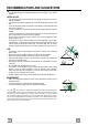
RECOMMENDATIONS AND SUGGESTIONS The Instructions for Use apply to several versions of this appliance. Accordingly, you may find descriptions of individual features that do not apply to your specific appliance. INSTALLATION • The manufacturer will not be held liable for any damages resulting from incorrect or improper installation. • The minimum safety distance between the cooker top and the extractor hood is 650 mm.
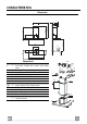
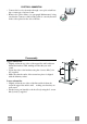
CHARACTERISTICS 126 max. 1000 650 min. 60 259 540 min. 670 81 63 41 Dimensions 898 300 260 485 108 150 Components Q.ty Product Components 1 Hood Body, complete with: Controls, Light, Blower, Filters 2 1 Telescopic Chimney comprising: 2.1 1 Upper Section 2.2 1 Lower Section 9 1 Reducer Flange ø 150-120 mm 14.1 2 Air Outlet Connection Extension 15 1 Air Outlet Connection Ref. Q.ty Installation Components 7.2.1 2 Upper Chimney Section Fixing Brackets 7.
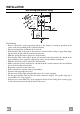
INSTALLATION 1÷2 Wall drilling and bracket fixing 11 116 116 650 min. 12a X 7.2.1 320 7.3 Wall marking: • Draw a vertical line on the supporting wall up to the ceiling, or as high as practical, at the centre of the area in which the hood will be installed. • Draw a horizontal line at 650 mm above the hob. • Place bracket 7.2.1 on the wall as shown about 1-2 mm from the ceiling or upper limit aligning the centre (notch) with the vertical reference line.
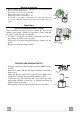
Mounting the hood body • Before attaching the hood body, tighten the two screws Vr located on the hood body mounting points. • Hook the hood body onto the screws 12a. • Fully tighten support screws 12a. • Adjust screws Vr to level the hood body. • If necessary, it is possible to fasten the hood to the wall using more screws with wall plugs, which can be positioned from inside the hood canopy.
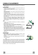
ELECTRICAL CONNECTION • Connect the hood to the mains through a two-pole switch having a contact gap of at least 3 mm. • Remove the grease filters (see paragraph Maintenance) being sure that the connector of the feeding cable is correctly inserted in the socket placed on the side of the fan. Flue assembly 7.2.1 Upper exhaust flue • Slightly widen the two sides of the upper flue and hook them behind the brackets 7.2.1, making sure that they are well seated.
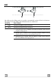
USE M L By pulling out the sliding panel it is possible to automatically activate all the hood functions. By simply closing the sliding panel all the functions are switched off. SWITCH FUNCTIONS L Light Switches the lighting system on and off M Motor Switches the extractor motor on and off 1. Low speed, used for a continuous and silent air change in the presence of light cooking vapour. 2.
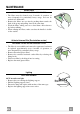
MAINTENANCE Grease filters CLEANING METAL SELF- SUPPORTING GREASE FILTERS • The filters must be cleaned every 2 months of operation, or more frequently for particularly heavy usage, and can be washed in a dishwasher. • Remove the filters one at a time by pushing them towards the back of the group and pulling down at the same time. • Wash the filters, taking care not to bend them. Allow them to dry before refitting. • When refitting the filters, make sure that the handle is visible on the outside.
CONSIGLI E SUGGERIMENTI Questo libretto di istruzioni per l'uso è previsto per più versioni dell'apparecchio. Possibile che siano descritti singoli particolari della dotazione, che non riguardano il Vostro apparecchio. INSTALLAZIONE • Il produttore declina qualsiasi responsabilità per danni dovuti ad installazione non corretta o non conforme alle regole dell’arte. • La distanza minima di sicurezza tra il Piano di cottura e la Cappa deve essere di 650 mm.
CARATTERISTICHE 126 max. 1000 650 min. 60 259 540 min. 670 81 63 41 Ingombro 898 300 260 485 108 150 Componenti Q.tà Componenti di Prodotto 1 Corpo Cappa completo di: Comandi, Luce, Gruppo Ventilatore, Filtri 2 1 Camino Telescopico formato da: 2.1 1 Camino Superiore 2.2 1 Camino Inferiore 9 1 Flangia di Riduzione ø 150-120 mm 14.1 2 Prolunga Raccordo Uscita Aria 15 1 Raccordo Uscita Aria Rif. Q.tà Componenti di Installazione 7.2.1 2 Staffe Fissaggio Camino Superiore 7.
INSTALLAZIONE 1÷2 Foratura Parete e Fissaggio Staffe 11 116 116 650 min. 12a X 7.2.1 320 7.3 Tracciare sulla Parete: • una linea Verticale fino al soffitto o al limite superiore, al centro della zona prevista per il montaggio della Cappa; • una linea Orizzontale a: 650 mm min. sopra il Piano di Cottura. • Appoggiare come indicato la Staffa 7.2.1 a 1-2 mm dal soffitto o dal limite superiore, allineando il suo centro (intagli) sulla linea Verticale di riferimento.
Montaggio Corpo Cappa • Prima di agganciare il Corpo Cappa, serrare le 2 Viti Vr situate sui punti di aggancio del Corpo Cappa. • Agganciare il Corpo Cappa alle Viti 12a. • Serrare definitivamente le Viti 12a di supporto. • Agire sulle Viti Vr per livellare il Corpo Cappa. • Nel caso si ritenga opportuno è possibile assicurare la cappa al muro per mezzo di altre viti con tassello, posizionabili dall’interno del corpo cappa.
CONNESSIONE ELETTRICA • Collegare la Cappa all’Alimentazione di Rete interponendo un Interruttore bipolare con apertura dei contatti di almeno 3 mm. • Rimuovere i Filtri antigrasso (vedi par. “Manutenzione”) e assicurarsi che il connettore del Cavo di alimentazione sia correttamente inserito nella presa dell’Aspiratore Montaggio Camino 7.2.1 Camino superiore • Allargare leggermente le due falde laterali, agganciarle dietro le Staffe 7.2.1 e richiuderle fino a battuta.
USO M L Le varie funzioni vengono attivate automaticamente con l’estrazione del carrello. Per spegnere le funzioni impostate sarà sufficiente richiudere il carrello. TASTO FUNZIONE L Luci Accende e spegne l’Impianto di Illuminazione. M Motore Accende e spegne il motore Aspirazione. 1. Velocità minima, adatta ad un ricambio d’aria continuo particolarmente silenzioso,in presenza di pochi vapori di cottura. 2.
MANUTENZIONE Filtri antigrasso PULIZIA FILTRI ANTIGRASSO METALLICI AUTOPORTANTI • Sono lavabili anche in lavastoviglie, e necessitano di essere lavati ogni 2 mesi circa di utilizzo o più frequentemente, per un uso particolarmente intenso. • Togliere i Filtri uno alla volta, spingendoli verso la parte posteriore del gruppo e tirando contemporaneamente verso il basso. • Lavare i Filtri evitando di piegarli, e lasciarli asciugare prima di rimontarli.
CONSEILS ET SUGGESTIONS La présente notice d'emploi vaut pour plusieurs versions de l'appareil. Elle peut contenir des descriptions d'accessoires ne figurant pas dans votre appareil. INSTALLATION • Le fabricant décline toute responsabilité en cas de dommage dû à une installation non correcte ou non conforme aux règles de l’art. • La distance minimale de sécurité entre le plan de cuisson et la hotte doit être de 650 mm au moins.
CARACTERISTIQUES 126 max. 1000 650 min. 60 259 540 min. 670 81 63 41 Encombrement 898 300 260 485 108 150 Composants Q.té Composants de Produit 1 Corps Hotte équipé de:Commandes, Lumière, Groupe Ventilateur,Filtres 2 1 Cheminée Télescopique formée de : 2.1 1 Cheminée Supérieure 2.2 1 Cheminée Inférieure 9 1 Flasque de Réduction ø 150-120 mm 14.1 2 Rallonge Raccord Sortie Air 15 1 Raccord Sortie Air Réf. Q.té Composants pour l ’installation 7.2.1 2 Brides Fixation Cheminée Supérieure 7.
INSTALLATION 1÷2 Perçage Paroi et Fixation Brides 11 116 116 650 min. 12a X 7.2.1 320 7.3 Tracer sur la paroi: • une ligne verticale allant jusqu’au plafond ou à la limite supérieure, au centre de la zone prévue pour le montage de la hotte; • une ligne horizontale à 650 mm min. au-dessus du plan de cuisson. • Poser comme indiqué une bride 7.2.1 sur la paroi à 1-2 mm du plafond ou de la limite supérieure, en alignant son centre (découpes) sur la ligne verticale de repère.
Montage Corps Hotte • Avant d’accrocher le corps hotte, serrer les deux vis Vr situées sur les points d’accrochage du corps hotte. • Accrocher le corps hotte aux vis 12a prévues à cet effet. • Serrer définitivement les vis 12a de support. • Agir sur les vis Vr pour niveler le corps hotte. • Si cela est jugé nécessaire, il est possible de fixer la hotte au mur au moyen de chevilles et vis supplémentaires qu’il faudra placer de l’intérieur du corps de la hotte.
BRANCHEMENT ELECTRIQUE • Brancher la hotte sur le secteur en interposant un interrupteur bipolaire avec ouverture des contacts d’au moins 3 mm. • Enlever les filtres à graisse (voir § "Entretien") et s'assurer que le connecteur du câble d'alimentation soit bien branché dans la prise du diffuseur. Montage Cheminée 7.2.1 Cheminée supérieure • Elargir légèrement les deux bords latériaux, et les accrocher derrières les brides 7.2.1 ; refermer jusqu’à la butée.
UTILISATION M L Les différentes fonctions de la hotte sont activées automatiquement avec l’ouverture du tiroir. Pour arrêter les fonctions sélectionnées il suffit de fermer le tiroir. TOUCHE FUNCTIONS L Lumières Allume et éteint l’éclairage. M Moteur Allume et éteint le moteur aspiration 1. Vitesse minimale, pour un rechange d’air permanent particulièrement silencieux en cas de faibles vapeurs de cuisson. 2.
ENTRETIEN Filtres anti-graisse NETTOYAGE FILTRES ANTI-GRAISSE METALLIQUES AUTOPORTEURS • Lavables au lave-vaisselle, ils doivent être lavés environ tous les 2 mois d’emploi ou plus fréquemment en cas d’emploi particulièrement intense. • Retirer les filtres l’un aprés l’autre, en les poussant vers la partie arrière du groupe et en tirant simultanément vers le bas. • Laver les filtres en évitant de les plier et les laisser sécher avant de les remonter.
EMPFEHLUNGEN UND HINWEISE Diese Gebrauchsanleitung gilt für mehrere Geräte-Ausführungen. Es ist möglich, dass einzelne Ausstattungsmerkmale beschrieben sind, die nicht auf Ihr Gerät zutreffen. MONTAGE • Das Gerät darf nur vom Fachpersonal angeschlossen werden. • Der Hersteller haftet nicht für Schäden, die auf eine fehlerhafte und unsachgemäße Montage zurückzuführen sind. • Der minimale Sicherheitsabstand zwischen Kochmulde und Haube muss 650 mm betragen.
CHARAKTERISTIKEN 126 max. 1000 650 min. 60 259 540 min. 670 81 63 41 Platzbedarf 898 300 260 485 108 150 Komponenten Pos. 1 St. 1 2 2.1 2.2 9 14.1 15 1 1 1 1 2 1 Produktkomponenten Haubenkörper mit Schaltern, Beleuchtung, Gebläsegruppe, Filter Teleskopkamin bestehend aus: oberer Kaminteil unterer Kaminteil Reduzierflansch ø 150-120 mm Verlängerung Luftaustritt-Anschlussstück Luftaustritt-Anschlussstück 15 14.1 7.3 12a 7.2.1 11 9 2.1 12c 2 Pos. 7.2.1 7.3 11 12a 12c DE St.
MONTAGE 1÷2 Bohren der Befestigungslöcher und Fixieren der Befestigungsbügel 11 116 116 650 min. 12a X 7.2.1 320 7.3 Achtung: Bitte beachten Sie bei der Montage das Gewicht der kompletten Haube. Die Tragfähigkeit der Decke oder alternativ der Trägerplatte für diese Zugbelastung muss vor der Montage geprüft und gegebenenfalls durch die Anbringung von geeigneten Befestigungs- oder Stabilisierungselementen hergestellt werden.
Montage des Haubenkörpers • Bevor der Haubenkörper eingehakt wird, die 2 Schrauben Vr bei den Haubenkörper-Anhakpunkten festziehen. • Den Haubenkörper bei den Schrauben 12a einhängen. • Die Halteschrauben 12a definitiv festziehen. • Den Haubenkörper mit Hilfe der Schrauben Vr ausrichten. • Die Haube kann bei Bedarf mit Hilfe weiterer Schrauben und Dübel von innen an der Wand gesichert werden.
Elektroanschluss • • Vor der Installation die Netzspannung durch herausdrehen der Sicherung oder ausschalten des Hauptschalters stromlos machen. Bei Anschluss der Haube an das Stromnetz muss ein zweipoliger Schalter mit einem Öffnungsweg von mindestens 3 mm zwischengeschaltet werden. Entfernen Sie die Fettfilter (s. Abschnitt „Wartung“) und versichern Sie sich, daß die Kabelverbindung in die Steckdose des Gebläses einwandfrei eingesteckt wird.
BEDIENUNG M L Die verschiedenen Funktionen werden automatisch beim Ausziehen des Wrasenleitschirms eingeschaltet. Um die Funktionen wieder auszuschalten, den Wrasenleitschirm einschieben. SCHALTER FUNKTION L Beleuchtung Schaltet die Beleuchtung ein und aus M Motor Schaltet den Gebläsemotor ein und aus 1. kleinste Gebläsestufe, diese Stufe ist für den geräuscharmen Dauerbetrieb der Haube bei geringer Wrasenentwicklung auf dem Kochfeld geeignet. 2.
WARTUNG Fettfilter SELBSTTRAGENDER METALLFETTFILTER REINIGUNG • Sie müssen nach 2-monatigem Betrieb bzw. bei starkem Einsatz auch häufiger gereinigt werden, was im Geschirrspüler möglich ist. • Die Filter nacheinander aushaken, indem sie auf die Rückseite der Gruppe geschoben und gleichzeitig nach unten gezogen werden. • Die Filter reinigen (darauf achten, sie nicht zu verbiegen) und vor der Remontage trocknen lassen.
TAVSIYELER VE ÖNERILER Bu kullanma talimatι birden fazla cihaz modeli için geçerlidir. Cihazιnιza uymayan bazι donanιm özellikleri tarif edilmiş olabilir. MONTAJ • Yalnιş veya eksik montajdan doğan herhangi bir zararιn sorumluluğu üreticiye ait değildir. • Davlumbaz ile pişirici cihazιn ocak kιsmι arasιndaki minimum güvenlik mesafesi 650 mm.dir. • Besleme voltajιnιn, davlumbaz içerisine yerleştirilen bilgi etiketinde belirtilenle aynι olup olmadιğιnι kontrol edin.
ÖZELLIKLER 126 max. 1000 650 min. 60 259 540 min. 670 81 63 41 Boyutlar 898 300 260 485 108 150 Parçalar Adet Ürünün parçaları 1 Şunlardan oluşan davlumbaz gövdesi: Kumandalar, Lamba, Fan grubu, Filtreler 2 1 Şunlardan oluşan teleskopik baca: 2.1 1 Üst baca 2.2 1 Alt baca 9 1 Redüksiyon Flanşı ø 150-120 mm 14.1 2 Hava Çıkışı Uzatma Rakoru 15 1 Hava Çıkışı Rakoru Ref. Adet Montaj Parçaları 7.2.1 2 Üst Baca Tesbit Braketleri 7.
MONTAJ 1÷2 Duvarın Delinmesi ve Braketlerin Sabitlenmesi 11 116 116 650 min. 12a X 7.2.1 320 7.3 Duvara şunları çiziniz: • Tavana yada üst sınıra kadar uzunan Dikey bir çizgi: Davlumbazın monte edileceği yerin tam merkezinden geçmelidir; • Tezgâh (setüstü ocak) yüzeyinden 650 mm mesafeden geçen bir Yatay çizgi. • Gösterildiği gibi Braketi 7.2.1 tavandan 1-2 mesafeye dayayınız ve bunun merkezini (çentik) Dikey referans çizgisine hizalayınız. • Braketin deliklerinin ortasından işaret koyunuz.
Davlumbaz Gövdesi Montajı • Davlumbaz Gövdesini kancalara takmadadan önce gövde üzerindeki kancalama noktalarında bulunan 2 adet vidayı Vr sıkınız. • Davlumbaz Gövdesini vidalara 12a takınız. • Destek vidalarını 12a nihai olarak sıkınız. • Vr vidalarına müdahale ederek Davlumbaz Gövdesi seviyesini hizalayınız. • Gerekli görülmesi halinde, gövdesinin iç kısmına yerleştirilebilecek iki adet dübelli vida ile, bacanın duvara tespit edilmesi mümkündür.
ELEKTRİK BAĞLANTISI • Davlumbazı şebeke cereyanına bağlarken aray temas aralığı en az 3 mm olan çift kutuplu bir elektrik anahtarı koyunuz. • Yağ tutucu filtreleri çıkarınız (bakınız "Bakım" paragrafı) ve besleme kablosu soketinin aspiratör prizine iyice takılmış olduğundan emin olunuz. Bacanın montajı Üst baca • İki yan kenarı hafifçe açınız, bunları braketlerin 7.2.1 arkasına geçiriniz ve tam dayanana kadar tekrar kapatınız.
KULLANIM M L Şaryonun dışarıya doğru kaydırılması ile farklı fonksiyonlar aktif hale gelmektedir. Bunların kapatılması için şaryonun yere kaydırılması yeterli olacaktır. DÜĞME İŞLEVİ L Işıklar Işıklandırma sistemini açar ve kapatır. M Motor Havalandırma motorunu açar ve kapatır. 1. Minimum hız; sessiz bir şekilde sürekli hava değişimini sağlar; az dumanlı durumlarda kullanılır. 2.
BAKIM Yağ tutucu filtreler METALİK YAĞ TUTUCU FİLTRELERİN TEMİZLENMESİ • Bu filtreler bulaşık makinasında da yıkanabilir ve normal kullanıldıklarında iki ayda bir, yoğun kullanım halinde ise daha sıkça yıkanmalarıı gereklidir. • Filtrleri, grubun arka tarafından ittirerek ve aynı anda aşağı doğru çekerek tek tek çıkarınız. • Filtreleri yıkarken eğip katlamayınız, tekrar monte etmeden önce de kurutunuz. • Monte ederken kulpun görünen dış tarafa doğru gelmesine dikkat ediniz.
Franke S.p.a. Via Pignolini,2 37019 Peschiera del Garda (VR) www.franke.