GB IT Instructions for use and installation Cooker Hood Istruzioni per l’uso e l’installazione Cappa FR Mode d’emploi et installation DE Bedienungsanleitung und Einrichtung TR Kullanım ve montaj talimatları CZ Hotte de Cuisine Dunstabzugshaube Davlumbaz Uživatelská Pøíruèka Kapuce FCR 908 TC
INDEX EN RECOMMENDATIONS AND SUGGESTIONS ......................................................................................................................3 CHARACTERISTICS..............................................................................................................................................................4 INSTALLATION .................................................................................................................................................................
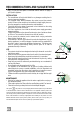
RECOMMENDATIONS AND SUGGESTIONS The Instructions for Use apply to several versions of this appliance. Accordingly, you may find descriptions of individual features that do not apply to your specific appliance. INSTALLATION • The manufacturer will not be held liable for any damages resulting from incorrect or improper installation.
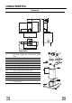
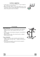
CHARACTERISTICS 126 max. 1000 650 min. 60 259 540 min. 670 81 63 41 Dimensions 898 300 260 485 108 150 Components Q.ty Product Components 1 Hood Body, complete with: Controls, Light, Blower, Filters 2 1 Telescopic Chimney comprising: 2.1 1 Upper Section 2.2 1 Lower Section 9 1 Reducer Flange ø 150-120 mm 14.1 2 Air Outlet Connection Extension 15 1 Air Outlet Connection Ref. Q.ty Installation Components 7.2.1 2 Upper Chimney Section Fixing Brackets 7.
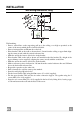
INSTALLATION 1÷2 Wall drilling and bracket fixing 11 116 116 650 min. 12a X 7.2.1 320 7.3 Wall marking: • Draw a vertical line on the supporting wall up to the ceiling, or as high as practical, at the centre of the area in which the hood will be installed. • Draw a horizontal line at 650 mm above the hob. • Place bracket 7.2.1 on the wall as shown about 1-2 mm from the ceiling or upper limit aligning the centre (notch) with the vertical reference line.
Mounting the hood body • Before attaching the hood body, tighten the two screws Vr located on the hood body mounting points. • Hook the hood body onto the screws 12a. • Fully tighten support screws 12a. • Adjust screws Vr to level the hood body. • If necessary, it is possible to fasten the hood to the wall using more screws with wall plugs, which can be positioned from inside the hood canopy.
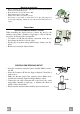
ELECTRICAL CONNECTION • Connect the hood to the mains through a two-pole switch having a contact gap of at least 3 mm. • Remove the grease filters (see paragraph Maintenance) being sure that the connector of the feeding cable is correctly inserted in the socket placed on the side of the fan. Flue assembly 7.2.1 Upper exhaust flue • Slightly widen the two sides of the upper flue and hook them behind the brackets 7.2.1, making sure that they are well seated.
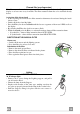
USE A B C D F E G H I L Control board Key Function A Switches the extractor motor on and off at the latest selected speed B Decreases the suction speed. C Increases the suction speed. D By pressing this key it is possible to start the intensive speed from any previously selected speed except the Delay-function and 24H-function. This speed has been timed at 10 minutes. After that time the system activates automatically the latest selected speed.
MAINTENANCE REMOTE CONTROL (OPTIONAL) The appliance can be controlled using a remote control powered by a 1.5 V carbon-zinc alkaline batteries of the standard LR03AAA type (not included). • Do not place the remote control near to heat sources. • Used batteries must be disposed of in the proper manner. Metal grease filters Metal filters can be washed also in a dish machine. They need to be washed every time a drop-symbol appears in the display or at least every two months.
Charcoal filter (recycling version) This filter cannot be washed or regenerated. It must be replaced when the C appears on the display or at least once every 4 months. The filter saturation alarm has to be activated already before. Activation of the alarm signal • In the recycling version hoods the filter saturation alarm must be activated during the installation or later. • Switch off the hood and the lights.
CONSIGLI E SUGGERIMENTI Questo libretto di istruzioni per l'uso è previsto per più versioni dell' apparecchio. É possibile che siano descritti singoli particolari della dotazione, che non riguardano il Vostro apparecchio. INSTALLAZIONE • Il produttore declina qualsiasi responsabilità per danni dovuti ad installazione non corretta o non conforme alle regole dell’arte.
CARATTERISTICHE 126 max. 1000 650 min. 60 259 540 min. 670 81 63 41 Ingombro 898 300 260 485 108 150 Componenti Q.tà Componenti di Prodotto 1 Corpo Cappa completo di: Comandi, Luce, Gruppo Ventilatore, Filtri 2 1 Camino Telescopico formato da: 2.1 1 Camino Superiore 2.2 1 Camino Inferiore 9 1 Flangia di Riduzione ø 150-120 mm 14.1 2 Prolunga Raccordo Uscita Aria 15 1 Raccordo Uscita Aria Rif. Q.tà Componenti di Installazione 7.2.1 2 Staffe Fissaggio Camino Superiore 7.
INSTALLAZIONE 1÷2 Foratura Parete e Fissaggio Staffe 11 116 116 650 min. 12a X 7.2.1 320 7.3 Tracciare sulla Parete: • una linea Verticale fino al soffitto o al limite superiore, al centro della zona prevista per il montaggio della Cappa; • una linea Orizzontale a: 650 mm min. sopra il Piano di Cottura. • Appoggiare come indicato la Staffa 7.2.1 a 1-2 mm dal soffitto o dal limite superiore, allineando il suo centro (intagli) sulla linea Verticale di riferimento.
Montaggio Corpo Cappa • Prima di agganciare il Corpo Cappa, serrare le 2 Viti Vr situate sui punti di aggancio del Corpo Cappa. • Agganciare il Corpo Cappa alle Viti 12a. • Serrare definitivamente le Viti 12a di supporto. • Agire sulle Viti Vr per livellare il Corpo Cappa. • Nel caso si ritenga opportuno è possibile assicurare la cappa al muro per mezzo di altre viti con tassello, posizionabili dall’interno del corpo cappa.
CONNESSIONE ELETTRICA • Collegare la Cappa all’Alimentazione di Rete interponendo un Interruttore bipolare con apertura dei contatti di almeno 3 mm. • Rimuovere i Filtri antigrasso (vedi par. “Manutenzione”) e assicurarsi che il connettore del Cavo di alimentazione sia correttamente inserito nella presa dell’Aspiratore Montaggio Camino 7.2.1 Camino superiore • Allargare leggermente le due falde laterali, agganciarle dietro le Staffe 7.2.1 e richiuderle fino a battuta.
USO A B C D F E G H I L Quadro comandi Tasto Funzione A Accende e spegne il motore di aspirazione all’ultima velocità utilizzata. B Decrementa la velocità di esercizio. C Incrementa la velocità di esercizio. D Attiva la velocità intensiva da qualsiasi velocità ad eccezione del Delay e del 24H, tale velocità è temporizzata a 10 minuti, al termine del tempo il sistema ritorna alla velocità precedentemente impostata. Adatta a fronteggiare le massime emissioni di fumi di cottura.
MANUTENZIONE TELECOMANDO (OPZIONALE) Questo apparecchio può essere comandato per mezzo di un telecomando, alimentato con pile alcaline zinco-carbone da 1,5 V del tipo standard LR03-AAA (non incluse). • Non riporre il telecomando in prossimità di fonti di calore. • Non disperdere le pile nell’ambiente, depositarle negli appositi contenitori.
Filtri antiodore al Carbone attivo (Versione Filtrante) Non è lavabile e non è rigenerabile, va sostituito quando sul display appare il simbolo C o almeno ogni 4 mesi. La segnalazione di Allarme va preventivamente attivata. Attivazione del segnale di allarme • Nelle Cappe in Versione Filtrante, la segnalazione di Allarme saturazione Filtri va attivata al momento dell’installazione o successivamente. • Spegnere le Luci e il Motore di aspirazione. • Premere il tasto E per circa 5 Sec.
CONSEILS ET SUGGESTIONS La présente notice d'emploi vaut pour plusieurs versions de l'appareil. Elle peut contenir des descriptions d'accessoires ne figurant pas dans votre appareil. INSTALLATION • Le fabricant décline toute responsabilité en cas de dommage dû à une installation non correcte ou non conforme aux règles de l’art.
CARACTERISTIQUES 126 max. 1000 650 min. 60 259 540 min. 670 81 63 41 Encombrement 898 300 260 485 108 150 Composants Q.té Composants de Produit 1 Corps Hotte équipé de:Commandes, Lumière, Groupe Ventilateur,Filtres 2 1 Cheminée Télescopique formée de : 2.1 1 Cheminée Supérieure 2.2 1 Cheminée Inférieure 9 1 Flasque de Réduction ø 150-120 mm 14.1 2 Rallonge Raccord Sortie Air 15 1 Raccord Sortie Air Réf. Q.té Composants pour l ’installation 7.2.1 2 Brides Fixation Cheminée Supérieure 7.
INSTALLATION 1÷2 Perçage Paroi et Fixation Brides 11 116 116 650 min. 12a X 7.2.1 320 7.3 Tracer sur la paroi: • une ligne verticale allant jusqu’au plafond ou à la limite supérieure, au centre de la zone prévue pour le montage de la hotte; • une ligne horizontale à 650 mm min. au-dessus du plan de cuisson. • Poser comme indiqué une bride 7.2.1 sur la paroi à 1-2 mm du plafond ou de la limite supérieure, en alignant son centre (découpes) sur la ligne verticale de repère.
Montage Corps Hotte • Avant d’accrocher le corps hotte, serrer les deux vis Vr situées sur les points d’accrochage du corps hotte. • Accrocher le corps hotte aux vis 12a prévues à cet effet. • Serrer définitivement les vis 12a de support. • Agir sur les vis Vr pour niveler le corps hotte. • Si cela est jugé nécessaire, il est possible de fixer la hotte au mur au moyen de chevilles et vis supplémentaires qu’il faudra placer de l’intérieur du corps de la hotte.
BRANCHEMENT ELECTRIQUE • Brancher la hotte sur le secteur en interposant un interrupteur bipolaire avec ouverture des contacts d’au moins 3 mm. • Enlever les filtres à graisse (voir § "Entretien") et s'assurer que le connecteur du câble d'alimentation soit bien branché dans la prise du diffuseur. Montage Cheminée 7.2.1 Cheminée supérieure • Elargir légèrement les deux bords latériaux, et les accrocher derrières les brides 7.2.1 ; refermer jusqu’à la butée.
UTILISATION A B C D F E G H I L Tableau des commandes Touche Fonction A Allume et éteint le moteur d’aspiration à la dernière vitesse utilisée B La vitesse de service diminue. C La vitesse de service augmente. D Active la vitesse intensive à partir de n’importe quelle vitesse, à l’exception des fonctions Retard et 24H. Cette vitesse est programmée pour durer 10 minutes, après quoi le système retourne à la vitesse réglée au préalable. Apte à faire face à une quantité maximale de fumées de cuisson.
ENTRETIEN TELECOMMANDE (FOURNIE SUR DEMANDE) Il est possible de commander cet appareil au moyen d’une télécommande, alimentée avec des piles alcalines zinc-charbon 1,5 V du type standard LR03-AAA (non compris). • Ne pas ranger la télécommande à proximité de sources de chaleur. • Ne pas jeter les piles; il faut les déposer dans les récipients de récolte spécialement prévus à cet effet.
Filtres anti-odeur au charbon actif (version filtrante) Il ne peut être ni lavé ni récupéré, il faut le changer quand le symbole C s’affiche ou au moins tous les 4 mois. Il faut tout d’abord activer le signal d’alarme. Activation du signal d’alarme • Pour les hottes en version filtrante, l’alarme indiquant la saturation des filtres doit être activée au moment de l’installation ou ultérieurement. • Éteindre les lumières et le moteur d’aspiration. • Appuyer sur la touche E pendant 5 sec.
EMPFEHLUNGEN UND HINWEISE Diese Gebrauchsanleitung gilt für mehrere Geräte-Ausführungen. Es ist möglich, dass einzelne Ausstattungsmerkmale beschrieben sind, die nicht auf Ihr Gerät zutreffen. MONTAGE • Der Hersteller haftet nicht für Schäden, die auf eine fehlerhafte und unsachgemäße Montage zurückzuführen sind.
CHARAKTERISTIKEN 126 max. 1000 650 min. 60 259 540 min. 670 81 63 41 Platzbedarf 898 300 260 485 108 150 Komponenten Pos. 1 St. 1 2 2.1 2.2 9 14.1 15 1 1 1 1 2 1 Produktkomponenten Haubenkörper mit Schaltern, Beleuchtung, Gebläsegruppe, Filter Teleskopkamin bestehend aus: oberer Kaminteil unterer Kaminteil Reduzierflansch ø 150-120 mm Verlängerung Luftaustritt-Anschlussstück Luftaustritt-Anschlussstück 15 14.1 7.3 12a 7.2.1 11 9 2.1 12c 2 Pos. 7.2.1 7.3 11 12a 12c DE St.
MONTAGE 1÷2 Bohren der Befestigungslöcher und Fixieren der Befestigungsbügel 11 116 116 650 min. 12a X 7.2.1 320 7.3 Achtung: Bitte beachten Sie bei der Montage das Gewicht der kompletten Haube. Die Tragfähigkeit der Decke oder alternativ der Trägerplatte für diese Zugbelastung muss vor der Montage geprüft und gegebenenfalls durch die Anbringung von geeigneten Befestigungs- oder Stabilisierungselementen hergestellt werden.
Montage des Haubenkörpers • Bevor der Haubenkörper eingehakt wird, die 2 Schrauben Vr bei den Haubenkörper-Anhakpunkten festziehen. • Den Haubenkörper bei den Schrauben 12a einhängen. • Die Halteschrauben 12a definitiv festziehen. • Den Haubenkörper mit Hilfe der Schrauben Vr ausrichten. • Die Haube kann bei Bedarf mit Hilfe weiterer Schrauben und Dübel von innen an der Wand gesichert werden.
Elektroanschluss • • Vor der Installation die Netzspannung durch herausdrehen der Sicherung oder ausschalten des Hauptschalters stromlos machen. Bei Anschluss der Haube an das Stromnetz muss ein zweipoliger Schalter mit einem Öffnungsweg von mindestens 3 mm zwischengeschaltet werden. Entfernen Sie die Fettfilter (s. Abschnitt „Wartung“) und versichern Sie sich, daß die Kabelverbindung in die Steckdose des Gebläses einwandfrei eingesteckt wird.
BEDIENUNG A B C D F E G H I L Bedienfeld Taste Funktion A Schaltet den Gebläsemotor in der zuletzt verwendeten Gebläsestufe ein und aus. B Verringert die laufende Gebläsestufe. C Steigert die laufende Gebläsestufe. D Aktiviert die Intensivstufe bei jeder Geschwindigkeit, mit Ausnahme der Funktionen Delay und 24H. Die Intensivstufe ist auf 10 Minuten begrenzt. Danach kehrt das System zur zuvor eingestellten Gebläsestufe zurück. Zum Beseitigen sehr starker Küchendünste geeignet.
WARTUNG FERNBEDIENUNG (OPTION) Dieses Gerät kann mit einer Fernbedienung gesteuert werden, welche mit alkalischen Zink-Kohle-Batterien 1,5 V des Standardtyps LR03-AAA versorgt wird (nicht enthalten). • Die Fernbedienung nicht in die Nähe von Hitzequellen legen. • Batterien müssen vorschriftsmäßig entsorgt werden. Metallfettfilter Die Filter können im Geschirrspüler gereinigt werden und sollten gereinigt werden, wenn das Symbol Tropfen auf dem Display erscheint bzw. mindestens ca.
Aktivkohle-Geruchsfilter (Umluftversion) Nicht waschbar und nicht regenerierbar. Ersetzen, wenn das Symbol C auf dem Display erscheint bzw. mindestens alle 4 Monate. Das Alarmsignal ist vorher zu aktivieren. Aktivierung des Alarmsignals • Bei Hauben in Umluftversion muss die Aktivierung der Filtersättigungsanzeige bei der Installation oder danach erfolgen. • Die Beleuchtung und den Gebläsemotor abschalten. • Die Taste E ca.
TAVSIYELER VE ÖNERILER Bu kullanma talimatι birden fazla cihaz modeli için geçerlidir. Cihazιnιza uymayan bazι donanιm özellikleri tarif edilmiş olabilir. MONTAJ • Yalnιş veya eksik montajdan doğan herhangi bir zararιn sorumluluğu üreticiye ait değildir. • Davlumbaz ile pişirici cihazιn ocak kιsmι arasιndaki minimum güvenlik mesafesi 650 mm.dir (bazı modeller daha alçak seviyede bir yüksekliğe kurulabilir, hacim ve kurulum ile ilgili paragraflara bakınız).
ÖZELLIKLER 126 max. 1000 650 min. 60 259 540 min. 670 81 63 41 Boyutlar 898 300 260 485 108 150 Parçalar Adet Ürünün parçaları 1 Şunlardan oluşan davlumbaz gövdesi: Kumandalar, Lamba, Fan grubu, Filtreler 2 1 Şunlardan oluşan teleskopik baca: 2.1 1 Üst baca 2.2 1 Alt baca 9 1 Redüksiyon Flanşı ø 150-120 mm 14.1 2 Hava Çıkışı Uzatma Rakoru 15 1 Hava Çıkışı Rakoru Ref. Adet Montaj Parçaları 7.2.1 2 Üst Baca Tesbit Braketleri 7.
MONTAJ 1÷2 Duvarın Delinmesi ve Braketlerin Sabitlenmesi 11 116 116 650 min. 12a X 7.2.1 320 7.3 Duvara şunları çiziniz: • Tavana yada üst sınıra kadar uzunan Dikey bir çizgi: Davlumbazın monte edileceği yerin tam merkezinden geçmelidir; • Tezgâh (setüstü ocak) yüzeyinden 650 mm mesafeden geçen bir Yatay çizgi. • Gösterildiği gibi Braketi 7.2.1 tavandan 1-2 mesafeye dayayınız ve bunun merkezini (çentik) Dikey referans çizgisine hizalayınız. • Braketin deliklerinin ortasından işaret koyunuz.
Davlumbaz Gövdesi Montajı • Davlumbaz Gövdesini kancalara takmadadan önce gövde üzerindeki kancalama noktalarında bulunan 2 adet vidayı Vr sıkınız. • Davlumbaz Gövdesini vidalara 12a takınız. • Destek vidalarını 12a nihai olarak sıkınız. • Vr vidalarına müdahale ederek Davlumbaz Gövdesi seviyesini hizalayınız. • Gerekli görülmesi halinde, gövdesinin iç kısmına yerleştirilebilecek iki adet dübelli vida ile, bacanın duvara tespit edilmesi mümkündür.
ELEKTRİK BAĞLANTISI • Davlumbazı şebeke cereyanına bağlarken aray temas aralığı en az 3 mm olan çift kutuplu bir elektrik anahtarı koyunuz. • Yağ tutucu filtreleri çıkarınız (bakınız "Bakım" paragrafı) ve besleme kablosu soketinin aspiratör prizine iyice takılmış olduğundan emin olunuz. Bacanın montajı Üst baca • İki yan kenarı hafifçe açınız, bunları braketlerin 7.2.1 arkasına geçiriniz ve tam dayanana kadar tekrar kapatınız.
KULLANIM A B C D F E G H I L Kumanda Tablosu Tuş A B C D E F G H I L İşlev Emme motorunu son kullanılan hızda açar ve kapatır. Çalışma hızını düşürür. Çalışma hızını yükseltir. Delay ve 24H haricinde, herhangi bir hızdan yoğun hıza geçer, bu hız 10 dakika zaman ayarlıdır, bu süre sonunda sistem daha önceden ayarlanan hıza geri döner. Pişirme anındaki dumanın fazla yayılmasını engellemeye uygundur. Motoru, her saatte bir 10 dakika 100 m3/h emiş hızında aktive eder, bitiminde motor durur.
BAKIM TELEKUMANDA (OPSİYONEL) Bu cihaza bir telekumanda ile de komut verilebilir; bu kumanda 1,5 Voltluk çinko-karbonlu LR03-AAA tipi standart alkalin pillerle çalışır (dahil değildir). • Telekumandayı ısı kaynakları yakınında bırakmaynız. • Pilleri çevreye atmayınız, bunlara ayrılmış çöp toplama kaplarına atınız. Yağlanmaya karşı metal filtreler Bulaşık makinasında yıkanabilirler ve yaklaşık her 2 aylık kullanım sonrasında veya özellikle yoğun kullanım durumunda daha sıklıkla yıkanmaları gerekir.
Aktif Karbonlu Kokuya Karşı Filtreler (Filtre Edici Versiyon) Yıkanamaz, yeniden kullanılamaz, ekranda C sembolü görüntülendiğinde veya en az 4 ayda bir değiştirilir. Alarm sinyali önceden aktive olur. Alarm sinyalinin aktive edilmesi • Filtre edici versiyon Davlumbazlarda, Filtreler doygunluk Alarm sinyali, kurulum anında veya devamında aktive olur. • Işıkları ve emme Motorunu kapatınız.
RADY A DOPORUČENÍ Tento návod k použití je společný pro několik verzí přístroje. Je tedy možné, že bude obsahovat popis některých komponentů, které jsou součástí vybavení jiného přístroje než je Váš. INSTALACE • Výrobce odmítá jakoukoli odpovědnost za škody způsobené nesprávnou instalací, která neodpovídá příslušným předpisům.
HLAVNÍ PARAMETRY 126 max. 1000 650 min. 60 259 540 min. 670 81 63 41 Prostorový rozměr 898 300 485 108 260 150 Díly 15 Č. 1 Poč. Díly spotřebiče 1 Těleso digestoře s ovládáním, osvětlením, jednotkou ventilátoru, filtry 2 1 Teleskopický komín tvořený: 2.1 1 Horním komínem 2.2 1 Dolním komínem 9 1 Redukční příruba ø 150-120 mm 14.1 2 Nástavec přípojky na výstupu vzduchu 15 1 Přípojka na výstupu vzduchu Č. Poč. Díly k instalaci 7.2.1 2 Upevňovací konzoly horního komínu 7.
INSTALACE 1÷2 Vyvrtání stěny a upevnění konzol 11 116 116 650 min. 12a X 7.2.1 320 7.3 Na stěně vyznačte: • svislou čáru až ke stropu nebo k horní ploše uprostřed prostoru plánovaného pro montáž digestoře; • vodorovnou čáru minimálně 650 mm nad varnou deskou. • Umístěte, jak je označeno, konzolu 7.2.1 do vzdálenosti 1-2 mm od stropu nebo od horní plochy a vyrovnejte její střed (zářezy) podle svislé orientační čáry. • Označte středy otvorů konzoly. • Umístěte, jak je označeno, konzolu 7.2.
Montáž tělesa digestoře • Před zaháknutím tělesa digestoře zašroubujte 2 šrouby Vr, které se nalézají na bodech zaháknutí tělesa digestoře. • Zahákněte těleso digestoře za šrouby 12a. • Úplně utáhněte upevňovací šrouby 12a. • Vyrovnejte těleso digestoře pomocí šroubů Vr. • Bude-li třeba, je možné digestoř upevnit ke stěně pomocí dalších šroubů s hmoždinkami, které se umístí dovnitř digestoře.
ELEKTRICKÉ PŘIPOJENÍ • Digestoř připojte k napájecí síti pomocí dvoupólového vypínače s nejméně 3 mm vzdáleností mezi kontakty. • Odstraňte tukové filtry (viz část “Údržba”) a ověřte si , že je konektor přívodního kabelu správně zasunutý do zásuvky ventilátoru. Montáž komínu Horní komín • Mírně roztáhněte oba boční okraje, zavěste je za konzoly 7.2.1 a uzavřete je až na doraz. • Pomocí čtyř šroubů 12c (2,9 x 9,5), které jsou součástí vybavení, je bočně upevněte ke konzolám.
POUŽITÍ A B C D F E G H I L Ovládací panel Tlačítko A B C D E F G H I L Funkce Displej Vypíná a zapíná motor nasávání s poslední použitou rychlostí. Snižuje provozní rychlost. Zvyšuje provozní rychlost. Spouští intenzivní rychlost z jakékoliv rychlosti, s výjimkou Delay a 24H, tato rychlost je omezena na dobu 10 minut, poté se systém navrátí k rychlosti nastavené předtím. Je vhodná pro použití při maximální produkci výparů z vaření.
ÚDRŽBA DÁLKOVÝ OVLADAČ (VOLITELNÉ) Tento spotřebič je možné ovládat dálkovým ovladačem napájeným dvěma alkalickými zinko-karbonovými bateriemi 1,5 v typu standard LR03-AAA (nezahrnutý). • Dálkový ovladač nepokládejte do blízkosti tepelných zdrojů. • Použité baterie nevyhazujte, ale zlikvidujte je ve speciálních kontejnerech. Kovové tukové filtry Tyto filtry lze mýt i v myčce.
Uhlíkové filtry proti zápachu (filtrační provedení) Tento filtr nelze mýt ani regenerovat. Je třeba jej vyměnit, když se na displeji zobrazí symbol C nebo alespoň každé čtyři měsíce. Signalizaci alarmu je třeba aktivovat předem. Aktivace signálu alarmu • U digestoří s filtračním provedením se signalizace nasycení filtrů aktivuje při instalaci nebo dodatečně. • Vypněte světla a motor nasávání.
Franke S.p.a. Via Pignolini,2 37019 Peschiera del Garda (VR) www.franke.