PRESTIGE 30” PRESTIGE 36” Range Hood Hotte Installation Instructions Use and Care Guide Instructions d’installation Mode d’emploi et d’entretien FDL 304 W FDL 364 W
INDEX WARNINGS AND REQUIREMENTS .....................................................................................................................................3 RECOMMENDATIONS AND SUGGESTIONS ......................................................................................................................6 DIMENSIONS and MAIN PARTS...........................................................................................................................................7 INSTALLATION ..............
READ AND SAVE THESE INSTRUCTIONS The Installer must leave these instructions with the homeowner. The homeowner must keep these instructions for future reference and for local electrical inspectors’ use. READ THESE INSTRUCTIONS BEFORE YOU START INSTALLING THIS RANGEHOOD WARNING: - TO REDUCE THE RISK OF A RANGE TOP GREASE FIRE: Never leave surface units unattended at high settings. Boilovers cause smoking and greasy spillovers that may ignite. Heat oils slowly on low or medium setting.
WARNING • • • • • • Venting system MUST terminate outside the home. DO NOT terminate the ductwork in an attic or other enclosed space. DO NOT use 4" laundry-type wall caps. Flexible-type ductwork is NOT recommended. DO NOT obstruct the flow of combustion and ventilation air. Failure to follow venting requirements may result in a fire. ELECTRICAL REQUIREMENTS A 120 volt, 60 Hz AC-only electrical supply is required on a separate 15 amp fused circuit. A timedelay fuse or circuit breaker is recommended.
cluding Fire-Rated Construction. Sufficient air is needed for proper combustion and exhausting of gases through the flue (chimney) of fuel burning equipment to prevent backdrafting. Follow the heating equipment manufacturer’s guideline and safety standards such as those published by the National Fire Protection Association (NFPA), and the American Society for Heating, Refrigeration and Air Conditioning Engineers (ASHRAE), and the local code authorities.
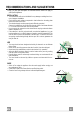
RECOMMENDATIONS AND SUGGESTIONS The Instructions for Use apply to several versions of this appliance. Accordingly, you may find descriptions of individual features that do not apply to your specific appliance. INSTALLATION • The manufacturer will not be held liable for any damages resulting from incorrect or improper installation. • Check that the main voltage corresponds to that indicated on the rating plate fixed to the inside of the hood.
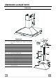
DIMENSIONS and MAIN PARTS Dimensions 7.3 Components Ref. Q.ty Product Components 1 1 Hood Body, complete with: Controls, Light, Blower, Filters 2 1 Telescopic Chimney comprising: 2.1 1 Upper Section 2.2 1 Lower Section 10 1 Damper 15 1 Air Outlet Connection Ref. Q.ty Installation Components 7.1 2 Hood Body Fixing Brackets 7.2.1 1 Upper Chimney Section Fixing Brackets 7.
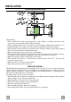
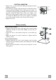
INSTALLATION Wall drilling and bracket fixing ÷1/16" X 7.3 4" 5/16 4" 5/16 H 24" 7.1 7"1/2 7.2.1 Wall marking: • Draw a vertical line on the supporting wall up to the ceiling, or as high as practical, at the center of the area in which the hood will be installed. • Draw a horizontal line at 24” above the hob for installation without the back panel, or at height H (height of the visible part of the panel) for installation with the back panel. • Place bracket 7.
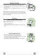
Mounting the hood body 12.d • Screw the two screws 12d supplied onto the brackets 7.1. • Hook the hood body onto the bracket 7.1, centring it around the vertical line. • Use the adjusting screws 12d underneath the hood to level the hood body. 7.1 Note: The Hood body should be secured to wall studs. If necessary, install a wood support behind the dry wall, flush mounted between 2 studs. This will provide the necessary structure and support for mounting.
ELECTRICAL CONNECTION • Remove the cover from the Field Wiring Compartment with a phillips screwdriver. • Feed the Power Supply Cable through the electrical knockout. Connect the Power Supply Cable to the range- hood cable. Attach the Power Supply Cable grounding lead to the green screw provided. Attach the White lead of the power supply to the White lead of the rangehood with a twist-on type wire connector.
USE S V1 V2 V3 L Control board L Light Switches the lighting system on and off. S Led Motor running led. V1 Motor Switches the extractor motor on and off at low speed. Used to provide a contin-uos and silent air change in the presence of light cooking vapours. V2 Speed V3 Intensive Medium speed, suitable for most operating conditions given the optimum treated air flox/noise level ratio. Maximum speed, used for eliminating the highest cooking vapour emission, including long periods.
CARE Metal Grease filters CLEANING METAL SELF- SUPPORTING GREASE FILTERS • The filters must be cleaned every 2 months of operation, or more frequently for particularly heavy usage, and can be washed in a dishwasher. • Remove the filters one by one by pushing them backwards and pulling them down contemporaneously. • Wash the filters. Pay attention not to bend them. Make sure that filters are completely dry before putting them into their seat.
TABLE DES MATIÈRES AVERTISSEMENT ET CONDITIONS N ÉCESSAIRES ......................................................................................................14 CONSEILS ET SUGGESTIONS ..........................................................................................................................................17 DIMENSIONS et PRINCIPALES PIÈCES............................................................................................................................18 INSTALLATION ..........
LIRE ET CONSERVER CES INSTRUCTIONS L’installateur doit laisser ces instructions au propriétaire. Le propriétaire doit conserver ces instructions en vue d’une utilisation subséquente et pour le bénéfice de l’inspecteur en électricité.
AVERTISSEMENT • • • • • • Le système d’évacuation DOIT se terminer à l’extérieur. N’ÉVACUEZ PAS le conduit dans un grenier ou dans tout autre espace fermé. N’UTILISEZ PAS un clapet de sécheuse à 4 pouces. ON DÉCONSEILLE l’emploi de conduit d’évacuation flexible. N’ENCOMBREZ PAS la circulation d’air. Le fait de ne pas respecter ces avertissements pourrait occasionner un incendie.
AVERTISSEMENT – POUR MINIMISER LES RISQUES D’INCENDIE, CHOC ÉLECTRIQUES OU BLESSURES, OBSERVER CETTE RÈGLE : l’installation et le raccordement électrique ne doivent être effectués que par un technicien(s) qualifié, selon tous les codes municipaux. Afin d’obtenir un rendement maximal en ce qui a trait à la combustion ainsi qu’à l’évacuation des gaz par la conduite de cheminée et pour qu’il n’y ait pas de reflux des gaz de combustion, une bonne aération est nécessaire pour tous les appareils à combustion.
CONSEILS ET SUGGESTIONS Les instructions d’utilisation s’applique à plusieurs versions de ce type d’appareil. En conséquence, il est possible que vous trouviez des descriptions de caractéristiques ne s'appliquant pas à votre appareil. INSTALLATION • Le fabricant décline toute responsabilité en cas de dommage dû à une installation inadéquate ou non conforme aux règles de l’art. • Vérifiez que la tension du secteur correspond à la valeur qui figure sur la plaquette apposée à l’intérieur de la hotte.
DIMENSIONS et PRINCIPALES PIÈCES Dimensions 7.3 Composantes Ref. 1 2 2.1 2.2 10 15 Ref. 7.1 7.2.1 7.
INSTALLATION Perçage de la paroi et fixation des brides ÷1/16" X 7.3 4" 5/16 4" 5/16 H 24" 7.1 7"1/2 7.2.1 Marquage au mur : • Tracer une ligne verticale sur le mur de support jusqu’au plafond, ou aussi haut que nécessaire, au centre de la surface sur laquelle la hotte sera installée. • Tracer une ligne horizontale à 24 po. au dessus du piquet pour installation sans panneau arrière, ou à la hauteur H (hauteur de la partie visible) pour l’installation avec panneau arrière. • Placer le support 7.
Montage du corps de la hotte • Vis les deux vis 12d accompagnant les supports 7.1. • Accrocher le corps de hotte sur le support 7.1, en le centrant autour de la ligne verticale. • Utiliser les vis de réglage 12d en dessous de la hotte pour mettre le corps de hotte à niveau. 12.d 7.1 Note : Le corps de hotte doit être fixé aux goujons muraux. Si nécessaire, installer un support en bois derrière le mur sec, monté à ras des 2 goujons. Cela assurera la structure requise et le support de montage.
BRANCHEMENT ÉLECTRIQUE • Retirer le couvercle du compartiment de filage à l’aide d’un tournevis Phillips. • Passer le câble d’alimentation dans la pastille enfonçable. Brancher le câble d’alimentation sur la hotte. Attacher le conducteur de mise à la terre du câble d’alimentation à la vis verte fournie. Attacher le fil blanc du câble d’alimentation au fil blanc de la hotte avec une cosse (connecteur de fils).
UTILISATION S V1 V2 V3 L Tableaux des commandes L Lumières Allume et éteint l’installation de l’éclairage. S Del Del allumage Moteur. V1 Moteur Met en marche et à l’arrêt le moteur aspiration à vitesse minimale, pour un rechange d’air permantent particulièrement silencieux en cas de faibles vapeurs de cuisson. V2 Vitesse Vitesse moyenne pour la plupart des conditions d’utilisation, étant donné le rapport optimal entre débit d’air traité et niveau sonore.
SOIN ET ENTRETIEN Filtres anti-graisse NETTOYAGE FILTRES ANTI-GRAISSE METALLIQUES AUTOPORTEURS • Lavables au lave-vaisselle, ils doivent être lavés environ tous les 2 mois d’emploi ou plus fréquemment en cas d’emploi particulièrement intense. • Enlevez les filtres l’un après l’autre en les soutenant avec une main et en tirant en même temps la poignée vers le bas avec l’autre main. • Laver les filtres en évitant de les plier et les laisser sécher avant de les remonter.
436003931_01 - 070711