IT Istruzioni per l’uso e l’installazione Cappa GB Instructions for use and installation FR Mode d’emploi et installation DE Bedienungsanleitung und Einrichtung TR Kullanım ve montaj talimatları Cooker Hood Hotte de Cuisine Dunstabzugshaube Davlumbaz FMY 907
Libretto di Istruzioni INDICE CONSIGLI E SUGGERIMENTI.............................................................................................................................................. 7 CARATTERISTICHE.............................................................................................................................................................. 8 INSTALLAZIONE.............................................................................................................................
Instructions Manual INDEX RECOMMENDATIONS AND SUGGESTIONS....................................................................................................................15 CHARACTERISTICS............................................................................................................................................................16 INSTALLATION .....................................................................................................................................................
Manuel d’Instructions SOMMAIRE CONSEILS ET SUGGESTIONS ..........................................................................................................................................23 CARACTERISTIQUES.........................................................................................................................................................24 INSTALLATION ...................................................................................................................................
Bedienungsanleitung INHALTSVERZEICHNIS EMPFEHLUNGEN UND HINWEISE....................................................................................................................................31 CHARAKTERISTIKEN .........................................................................................................................................................32 MONTAGE.....................................................................................................................................
Kullanim Kilavuku IÇERIKLER TAVSIYELER VE ÖNERILER..............................................................................................................................................39 ÖZELLIKLER........................................................................................................................................................................40 MONTAJ..................................................................................................................................
CONSIGLI E SUGGERIMENTI INSTALLAZIONE • Il produttore declina qualsiasi responsabilità per danni dovuti ad installazione non corretta o non conforme alle regole dell’arte. • Verificare che la tensione di rete corrisponda a quella riportata nella targhetta posta all’interno della Cappa. • Per Apparecchi in Classe Ia accertarsi che l’impianto elettrico domestico garantisca un corretto scarico a terra. • Collegare la Cappa all’uscita dell’aria aspirata con tubazione di diametro pari o superiore a 120 mm.
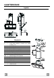
CARATTERISTICHE 259 80 Ingombro 15 14.1 Componenti Q.tà Componenti di Prodotto 1 Corpo Cappa completo di: Comandi, Luce, Gruppo Ventilatore, Filtri 2 1 Camino Telescopico formato da: 2.1 1 Camino Superiore 2.2 1 Camino Inferiore 9 1 Flangia di Riduzione ø 150-120 mm 14.1 2 Prolunga Raccordo Uscita Aria 15 1 Raccordo Uscita Aria Rif. Q.tà Componenti di Installazione 7.2.1 2 Staffe Fissaggio Camino Superiore 7.3 1 Staffa Sostegno Raccordo 11 6 Tasselli 12a 6 Viti 4,2 x 44,4 12c 6 Viti 2,9 x 9,5 Q.
INSTALLAZIONE 12 Foratura Parete e Fissaggio Staffe X 7.2.1 11 116 116 1075 min 12a Tracciare sulla Parete: • una linea Verticale fino al soffitto o al limite superiore, al centro della zona prevista per il montaggio della Cappa; • una linea Orizzontale a: 1075 mm min. sopra il Piano di Cottura. • Appoggiare come indicato la Staffa 7.2.1 a 1-2 mm dal soffitto o dal limite superiore, allineando il suo centro (intagli) sulla linea Verticale di riferimento. • Segnare i centri dei Fori della Staffa.
Montaggio Corpo Cappa Vr • Prima di agganciare il Corpo Cappa, serrare le 2 Viti Vr situate sui punti di aggancio del Corpo Cappa. • Agganciare il Corpo Cappa alle Viti 12a. • Serrare definitivamente le Viti 12a di supporto. • Agire sulle Viti Vr per livellare il Corpo Cappa.
CONNESSIONE ELETTRICA • Collegare la Cappa all’Alimentazione di Rete interponendo un Interruttore bipolare con apertura dei contatti di almeno 3 mm. • Rimuovere i Filtri antigrasso (vedi par. “Manutenzione”) e assicurarsi che il connettore del Cavo di alimentazione sia correttamente inserito nella presa dell’Aspiratore 7.2.1 Montaggio Camino Camino superiore • Allargare leggermente le due falde laterali, agganciarle dietro le Staffe 7.2.1 e richiuderle fino a battuta.
USO A B C D E F G H Quadro comandi Tasto Funzione Display A Accende e spegne il motore di aspirazione Visualizza la velocità impostata all’ultima velocità utilizzata. B Decrementa la velocità di esercizio. C Incrementa la velocità di esercizio. D Attiva la velocità intensiva da qualsiasi velo- Visualizza HI e il punto in basso a destra lamcità anche da motore spento, tale velocità è peggia una volta al secondo.
MANUTENZIONE Pulizia dei Confort Panel • Aprire il Confort Panel tirandolo. • Sganciare il pannello dal corpo cappa facendo scorrere l’apposita leva del perno di fissaggio. • Il confort panel non va assolutamente lavato in lavastoviglie. • Pulirlo esternamente con un panno umido e detersivo liquido neutro. • Pulirlo anche internamente utilizzando un panno umido e detergente neutro; non utilizzare panni o spugne bagnate, né getti d’acqua; non utilizzare sostanze abrasive.
Filtri antiodore al Carbone attivo (Versione Filtrante) • Non è lavabile e non è rigenerabile, va sostituito quando sul display appare EF o almeno ogni 4 mesi. Attivazione del segnale di allarme • Nelle Cappe in Versione Filtrante, la segnalazione di Allarme saturazione Filtri va attivata al momento dell’installazione o successivamente. • Spegnere le Luci e il Motore di aspirazione. • Scollegare la cappa dall’alimentazione di rete. • Ripristinare il collegamento tenendo premuto il tasto B.
RECOMMENDATIONS AND SUGGESTIONS INSTALLATION • The manufacturer will not be held liable for any damages resulting from incorrect or improper installation. • Check that the mains voltage corresponds to that indicated on the rating plate fixed to the inside of the hood. • For Class I appliances, check that the domestic power supply guarantees adequate earthing. Connect the extractor to the exhaust flue through a pipe of minimum diameter 120 mm. The route of the flue must be as short as possible.
CHARACTERISTICS 259 80 Dimensions 15 14.1 Components Q.ty Product Components 1 Hood Body, complete with: Controls, Light, Blower, Filters 2 1 Telescopic Chimney comprising: 2.1 1 Upper Section 2.2 1 Lower Section 9 1 Reducer Flange ø 150-120 mm 14.1 2 Air Outlet Connection Extension 15 1 Air Outlet Connection Ref. Q.ty Installation Components 7.2.1 2 Upper Chimney Section Fixing Brackets 7.3 1 Air Outlet Connection Support 11 6 Wall Plugs 12a 6 Screws 4,2 x 44,4 12c 6 Screws 2,9 x 9,5 Q.
INSTALLATION 12 Wall drilling and bracket fixing X 7.2.1 11 116 116 1075 min 12a Wall marking: • Draw a vertical line on the supporting wall up to the ceiling, or as high as practical, at the centre of the area in which the hood will be installed. • Draw a horizontal line at 1075 mm above the hob. • Place bracket 7.2.1 on the wall as shown about 1-2 mm from the ceiling or upper limit aligning the centre (notch) with the vertical reference line.
Mounting the hood body Vr • Before attaching the hood body, tighten the two screws Vr located on the hood body mounting points. • Hook the hood body onto the screws 12a. • Fully tighten support screws 12a. • Adjust screws Vr to level the hood body. 12a Connections DUCTED VERSION AIR EXHAUST SYSTEM When installing the ducted version, connect the hood to the chimney using either a flexible or rigid pipe ø 150 or 120 mm, the choice of which is left to the installer.
ELECTRICAL CONNECTION • Connect the hood to the mains through a two-pole switch having a contact gap of at least 3 mm. • Remove the grease filters (see paragraph Maintenance) being sure that the connector of the feeding cable is correctly inserted in the socket placed on the side of the fan. 7.2.1 Flue assembly Upper exhaust flue • Slightly widen the two sides of the upper flue and hook them behind the brackets 7.2.1, making sure that they are well seated.
USE A B C D E F G H Control board Key B Function Display Switches the extractor motor on and off at the Indicates the selected speed. latest selected speed Decreases the suction speed. C Increases the suction speed. D By pressing this key it is possible to activate HI appears. The spot down on the right side the intensive speed from any previously se- flashes once a second. lected speed. The intensive speed can be activated even when the motor is OFF. This speed has been timed at 10 minutes.
MAINTENANCE Cleaning the Comfort Panels • Pull the Comfort Panel to open it. • Disconnect the panel from the hood canopy by sliding the fixing pin lever. • The comfort panel must never be washed in a dishwasher. • Clean the outside using a damp cloth and neutral liquid detergent. • Clean the inside as well using a damp cloth and neutral detergent; do not use wet cloths or sponges, or jets of water; do not use abrasive substances.
Charcoal filter (recycling version) • This filter cannot be washed or regenerated. It must be replaced when the EF appears on the display or at least once every 4 months. Activation of the alarm signal • In the recycling version hoods the filter saturation alarm must be activated during the installation or later. • Switch off the hood and the lights. • Disconnect the hood from the mains supply. • When restoring the connection press and hold B-key.
CONSEILS ET SUGGESTIONS INSTALLATION • Le fabricant décline toute responsabilité en cas de dommage dû à une installation non correcte ou non conforme aux règles de l’art. • Vérifier que la tension du secteur correspond à la valeur qui figure sur la plaquette apposée à l’intérieur de la hotte. • Pour les Appareils appartenant à la Ière Classe, veiller à ce que la mise à la terre de l’installation électrique domestique ait été effectuée conformément aux normes en vigueur.
CARACTERISTIQUES 259 80 Encombrement 15 14.1 Composants Q.té Composants de Produit 1 Corps Hotte équipé de:Comandes, Lumière,Groupe Ventilateur,Filtres 2 1 Cheminée Télescopique formée de : 2.1 1 Cheminée Supérieure 2.2 1 Cheminée Inférieure 9 1 Flasque de Réduction ø 150-120 mm 14.1 2 Rallonge Raccord Sortie Air 15 1 Raccord Sortie Air Réf. Q.té Composants pour l ’installation 7.2.1 2 Brides Fixation Cheminée Supérieure 7.
INSTALLATION 12 Perçage Paroi et Fixation Brides X 7.2.1 11 116 116 1075 min 12a Tracer sur la paroi: • une ligne verticale allant jusqu’au plafond ou à la limite supérieure, au centre de la zone prévue pour le montage de la hotte; • une ligne horizontale à 1075 mm min. au-dessus du plan de cuisson. • Poser comme indiqué une bride 7.2.1 sur la paroi à 1-2 mm du plafond ou de la limite supérieure, en alignant son centre (découpes) sur la ligne verticale de repère.
Vr Montage Corps Hotte • Avant d’accrocher le corps hotte, serrer les deux vis Vr situées sur les points d’accrochage du corps hotte. • Accrocher le corps hotte aux vis 12a prévues à cet effet. • Serrer définitivement les vis 12a de support. • Agir sur les vis Vr pour niveler le corps hotte. 12a Branchements SORTIE AIR VERSION ASPIRANTE En cas d’installation en version aspirante, brancher la hotte à la tuyauterie de sortie via un tube ri-gide ou flexible de ø 150 ou 120 mm, au choix de l’installateur.
BRANCHEMENT ELECTRIQUE • Brancher la hotte sur le secteur en interposant un interrupteur bipolaire avec ouverture des contacts d’au moins 3 mm. • Enlever les filtres à graisse (voir § "Entretien") et s'assurer que le connecteur du câble d'alimentation soit bien branché dans la prise du diffuseur. 7.2.1 Montage Cheminée Cheminée supérieure • Elargir légèrement les deux bords latériaux, et les accrocher derrières les brides 7.2.1 ; refermer jusqu’à la butée.
UTILISATION A B C D E F G H Tableau des commandes Touche Fonction A Allume et éteint le moteur d’aspiration à la dernière vitesse utilisée B Diminue la vitesse de service C Augmente la vitesse de service D Active la vitesse intensive à partir de n’importe quelle vitesse, même du moteur arrêté. Cette vitesse est programmée pour durer 10 minutes, après quoi le système retourne à la vitesse réglée au préalable. Sert à faire face à une quantité maximale de fumées de cuisson.
ENTRETIEN Nettoyage des Confort Panel • Ouvrir le Confort Panel, en tirant ce dernier. • Décrocher le panneau du corps de la hotte, en faisant coulisser le levier du goujon de fixation spécialement prévu. • En aucun cas, le confort panel ne doit être lavé au lave-vaisselle. • Le nettoyer à l’extérieur à l’aide d’un chiffon humide et d’un détergent liquide neutre.
Filtre anti-odeur au charbon actif (version filtrante) • Il ne peut être ni lavé ni récupéré, il faut le changer quand EF s’affiche ou au moins tous les 4 mois. Déclenchement du signal d’alarme • Pour les Hottes en Version Filtrante, l’alarme indiquant la saturation des Filtres doit être activée au moment de l’installation ou ultérieurement. • Éteindre les lumières et le moteur d’aspiration. • Débrancher la hotte du réseau électrique. • Rétablir le branchement en appuyant sur la touche B.
EMPFEHLUNGEN UND HINWEISE MONTAGE • Der Hersteller haftet nicht für Schäden, die auf eine fehlerhafte und unsachgemäße Montage zurückzuführen sind. • Prüfen, ob die Netzspannung mit dem Wert auf dem im Haubeninneren angebrachten Schild übereinstimmt. • Bei Geräten der Klasse I ist sicherzustellen, dass die elektrische Anlage des Wohnhauses über eine vorschriftsmäßige Erdung verfügt. • Das Anschlussrohr der Haube zur Luftaustrittsöffnung muss einen Durchmesser von 120 mm oder darüber aufweisen.
CHARAKTERISTIKEN 259 80 Platzbedarf 15 14.1 Komponenten Pos. 1 St. 1 2 2.1 2.2 9 14.1 15 Pos. 7.2.1 7.3 11 12a 12c 1 1 1 1 2 1 St. 2 1 6 6 6 St.
MONTAGE 12 Bohren der Befestigungslöcher und Fixieren der Befestigungsbügel X 7.2.1 11 116 116 1075 min 12a Nachstehende Linien an die Wand zeichnen: • eine vertikale Linie bis zur Decke oder oberen Begrenzung, und zwar in der Mitte des Bereiches, in dem die Haube montiert werden soll; • eine horizontale Linie: mit einem minimalen Abstand von 1075 mm zur Kochfläche. • Einen Bügel 7.2.
Montage des Haubenkörpers Vr • Bevor der Haubenkörper eingehakt wird, die 2 Schrauben Vr bei den Haubenkörper-Anhakpunkten festziehen. • Den Haubenkörper bei den Schrauben 12a einhängen. • Die Halteschrauben 12a definitiv festziehen. • Den Haubenkörper mit Hilfe der Schrauben Vr ausrichten. 12a Anschlüss in abluftversion Bei Abluftbetrieb kann die Haube vom Installateur wahlweise mittels Rohr oder Schlauch (ø 150 oder 120 mm) an die Außenrohrleitung angeschlossen werden.
ELEKTROANSCHLUSS • Bei Anschluss der Haube an das Stromnetz muss ein zweipoliger Schalter mit einem Öffnungsweg von mindestens 3 mm zwischengeschaltet werden. • Entfernen Sie die Fettfilter (s. Abschnitt „Wartung“) und versichern Sie sich, daß die Kabelverbindung in die Steckdose des Gebläses einwandfrei eingesteckt wird. 7.2.1 Kaminmontage Oberer Kaminteil • Die beiden seitlichen Schenkel leicht auseinanderbiegen, hinter den Bügeln 7.2.1 einhängen und bis zum Anschlag wieder schließen.
BEDIENUNG A B C D E F G H Bedienblende Taste Funktion A Schaltet den Motor der Absauganlage bei der zuletzt verwendeten Geschwindigkeit ein und aus. B Vermindert die Betriebsgeschwindigkeit. C Erhöht die Betriebsgeschwindigkeit. D Aktiviert von jeder Geschwindigkeit aus, auch bei abgestelltem Motor, die Intensivgeschwindigkeit, die auf 10 Minuten zeitgeregelt ist. Nach Ablauf dieser Zeit kehrt das System zu der zuvor eingestellten Geschwindigkeit zurück.
WARTUNG Reinigung der Confort Panel • Den Confort Panel durch Ziehen öffnen. • Die Platte vom Haubenkörper aushaken, indem der Hebel des Befestigungsstiftes verschoben wird. • Die Confort panel darf keinesfalls im Geschirrspüler gewaschen werden. • Außen mit einem feuchten Lappen und neutralem Flüssigreiniger säubern. • Innen mit einem feuchten Lappen und neutralem Reinigungsmittel säubern; keine nassen Lappen oder Schwämme oder Wasserstrahl verwenden; kein Scheuermittel verwenden.
Aktivkohle-Geruchsfilter (Filterversion) • Der Aktivkohlefilter ist weder waschbar, noch regenerierbar und muss ausgewechselt werden, wenn am Display die Aufschrift EF erscheint, oder nach mindestens 4 Monaten. Aktivierung des Alarmsignals • Bei den Filterversionen der Abzugshauben wird die Alarmanzeige für Filtersättigung im Augenblick der Installation oder in der Folge aktiviert. • Die Beleuchtung und den Abzugsmotor ausschalten. • Die Abzugshaube von der Netzversorgung trennen.
TAVSIYELER VE ÖNERILER MONTAJ • Yalnιş veya eksik montajdan doğan herhangi bir zararιn sorumluluğu üreticiye ait değildir. • Besleme voltajιnιn, davlumbaz içerisine yerleştirilen bilgi etiketinde belirtilenle aynι olup olmadιğιnι kontrol edin. • Sιnιf I elektrikli aletleri için, güç kaynağιnιn yeterli topraklamayι sağlayιp sağlamadιğιnι kontrol edin. Minimum 120 mm çapιnda bir boru yoluyla davlumbazι çιkιş bacasιna bağlayιn. Baca bağlantιsι mümkün oldu- ğunca kιsa olmalιdιr.
ÖZELLIKLER 259 80 Boyutlar 15 Parçalar Adet Ürünün parçaları 1 Şunlardan oluşan davlumbaz gövdesi: Kumandalar, Lamba, Fan grubu, Filtreler 2 1 Şunlardan oluşan teleskopik baca: 2.1 1 Üst baca 2.2 1 Alt baca 9 1 Redüksiyon Flanşı ø 150-120 mm 14.1 2 Hava Çıkışı Uzatma Rakoru 15 1 Hava Çıkışı Rakoru Ref. Adet Montaj Parçaları 7.2.1 2 Üst Baca Tesbit Braketleri 7.3 1 Rakor Destek Braketi 11 6 Dübeller 12a 6 Vidalar 4,2 x 44,4 12c 6 Vidalar 2,9 x 9,5 Adet Belgeler 1 Talimat Kılavuzu 14.1 Ref. 1 TR 7.
MONTAJ 12 Duvarın Delinmesi ve Braketlerin Sabitlenmesi X 7.2.1 11 116 116 1075 min 12a Duvara şunları çiziniz: • Tavana yada üst sınıra kadar uzunan Dikey bir çizgi: Davlumbazın monte edileceği yerin tam merkezinden geçmelidir; • Tezgâh (setüstü ocak) yüzeyinden 1075 mm mesafeden geçen bir Yatay çizgi. • Gösterildiği gibi Braketi 7.2.1 tavandan 1-2 mesafeye dayayınız veya bunun merkezini (çentik) Dikey referans çizgisine hizalayınız. • Braketin deliklerinin ortasından işaret koyunuz.
Davlumbaz Gövdesi Montajı Vr • Davlumbaz Gövdesini kancalara takmadadan önce gövde üzerindeki kancalama noktalarında bulunan 2 adet vidayı Vr sıkınız. • Davlumbaz Gövdesini vidalara 12a takınız. • Destek vidalarını 12a nihai olarak sıkınız. • Vr vidalarına müdahale ederek Davlumbaz Gövdesi seviyesini hizalayınız. 12a Bağlantılar ASPİRATÖRLÜ MODEL HAVA ÇIKIŞI Aspiratörlü modelin montajı için, davlumbaz, montörün seçeceği 150 yada 120 mm çapında sert veya esnek bir boru ile çıkış kanalına bağlanmalıdır.
ELEKTRİK BAĞLANTISI • Davlumbazı şebeke cereyanına bağlarken aray temas aralığı en az 3 mm olan çift kutuplu bir elektrik anahtarı koyunuz. • Yağ tutucu filtreleri çıkarınız (bakınız "Bakım" paragrafı) ve besleme kablosu soketinin aspiratör prizine iyice takılmış olduğundan emin olunuz. 7.2.1 Bacanın Montajı Üst Baca • İki yan kenarı hafifçe açınız, bunları braketlerin 7.2.1 arkasına geçiriniz ve tam dayanana kadar tekrar kapatınız.
KULLANIM A B C D E F G H Kumanda Tablosu Tuş Fonksiyon Gösterge A Aspiratör motorunu, kullanılan en son hızda Ayarlanan hızı görüntüler. açıp kapatır. B O an devrede olan hızı düşürür. C O an devrede olan hızı arttırır. D Motor kapalıyken bile herhangi bir hızdan yoğun hızı devreye alır; bu hız 10 dakikaya ayarlıdır ve bu sürenin sonunda sistem daha önce ayarlanmış olan hıza döner. En yükek yoğunluktaki pişirme dumanlarının tahliyesine uygundur.
BAKIM Konfor Panelleri’nin Temizlenmesi • Çekerek Konfor Paneli’ni açınız. • Sabitleme piminin kolunu kaydırarak paneli davlumbaz gövdesinden kurtarınız. • Konfor paneli, asla bulaşık makinasında yıkanmaz. • Dış tarafını nemli bir bez ve nötr sıvı deterjan ile temizleyiniz. • İç kısmını da nemli bez ve nötr sıvı deterjan kullanarak temizleyebilirsiniz. Islak bez ya da sünger kullanmayınız, su püskürtmeyiniz ve aşındırıcı-yıpratıcı maddeler kullanmaktan kaçınınız.
Aktif karbonlu koku giderici filtreler (Filtreli Model) • Aktif karbonlu koku giderici filtrelerin yıkanması ve rejenere edilmeleri mümkün değildir, göstergede EF işareti görüntülendiğinde ya da en az 4 ayda bir değiştirilmeleri gerekir. Alarm sinyalinin devreye alınması • Filtrelerin doyum noktasına geldiğini bildiren alarm sinyali montaj sırasında devreye alınabileceği gibi, Filtreli Model davlumbazlarda daha sonra da devreye alınabilir. • Lambaları ve Aspiratör Motorunu kapatınız.
Dir. 89/336/CEE 73/23/CEE 93/68/CEE Il simbolo sul prodotto o sulla confezione indica che il prodotto non deve essere considerato come un normale rifiuto domestico, ma deve essere portato nel punto di raccolta appropriato per il riciclaggio di apparecchiature elettriche ed elettroniche. Provvedendo a smaltire questo prodotto in modo appropriato, si contribuisce a evitare potenziali conseguenze negative per l’ambiente e per la salute, che potrebbero derivare da uno smaltimento inadeguato del prodotto.