GB Instructions for use and installation Cooker Hood IT Istruzioni per l’uso e l’installazione FR Mode d’emploi et installation DE Bedienungsanleitung und Einrichtung TR Kullanım ve montaj talimatları HR Upute za korištenje i instalaciju PL Instrukcja obsługi i instalacji Cappa Hotte de Cuisine Dunstabzugshaube Davlumbaz Napa Okap kuchenny FPL 607 I FPL 907 I FPL 457 I XS 645H FPL 607 I XS 645H FPL 907 I XS 645H
Instructions Manual INDEX RECOMMENDATIONS AND SUGGESTIONS ......................................................................................................................9 CHARACTERISTICS............................................................................................................................................................10 INSTALLATION ..................................................................................................................................................
Libretto di Istruzioni INDICE CONSIGLI E SUGGERIMENTI ............................................................................................................................................20 CARATTERISTICHE ............................................................................................................................................................21 INSTALLAZIONE..............................................................................................................................
Manuel d’Instructions SOMMAIRE CONSEILS ET SUGGESTIONS ..........................................................................................................................................31 CARACTERISTIQUES .........................................................................................................................................................32 INSTALLATION .................................................................................................................................
Bedienungsanleitung INHALTSVERZEICHNIS EMPFEHLUNGEN UND HINWEISE....................................................................................................................................42 CHARAKTERISTIKEN..........................................................................................................................................................43 MONTAGE....................................................................................................................................
Kullanim Kilavuku IÇERIKLER TAVSIYELER VE ÖNERILER ..............................................................................................................................................53 ÖZELLIKLER ........................................................................................................................................................................54 MONTAJ ..............................................................................................................................
Uputstva za Korištenje KAZALO SAVJETI I PREPORUKE......................................................................................................................................................64 SVOJSTVA PROIZVODA.....................................................................................................................................................65 INSTALIRANJE...............................................................................................................................
Instrukcja Obslugi SPIS TRE!CI UWAGI I SUGESTIE.............................................................................................................................................................75 WŁA!CIWO!CI TECHNICZNE............................................................................................................................................76 INSTALACJA ................................................................................................................................
RECOMMENDATIONS AND SUGGESTIONS The Instructions for Use apply to several versions of this appliance. Accordingly, you may find descriptions of individual features that do not apply to your specific appliance. INSTALLATION • The manufacturer will not be held liable for any damages resulting from incorrect or improper installation. • The minimum safety distance between the cooker top and the extractor hood is 650 mm.
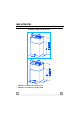
CHARACTERISTICS Dimensions * ** * ** The dimensions depend on the chosen version * Dimensions of the hood in ducting version. ** Dimensions of the hood in recycling version.
Components Ref. Q.ty Product Components 1 1 Hood Body, complete with: Controls, Light, Blower, Filters Upper Chimney Telescopic frame complete with extractor, consisting of: Upper frame Lower frame Reducer Flange ø 150-120 mm (Optional) Gasket Hood Body Air Outlet Extension Piece Air Outlet Connection Pipe clamps Fixing Part of the upper Chimney 2 1 7.1 1 7.1a 1 7.1b 1 9 1 13 1 14 1 15 1 25 2 26 1 Ref. Q.
INSTALLATION Drilling the Ceiling/shelf and fixing the frame DRILLING THE CEILING/SHELF • Use a plumb line to mark the centre of the hob on the ceiling/support shelf. • Place the drilling template 21 provided on the ceiling/support shelf, making sure that the template is in the correct position by lining up the axes of the template with those of the hob. • Mark the centres of the holes in the template.
FIXING THE FRAME If you wish to adjust the height of the frame, proceed as follows: • Unfasten the metric screws joining the two columns, located at the sides of the frame. • Adjust the frame to the height required, then replace all the screws removed as above. • Fix the Fixing Part of the Upper Chimney 26 to the hanging kit using the 2 screws 12w (M3 x 8). • Lift up the frame, fit the frame slots onto the screws up to the slot end positions.
Ducted version air exhaust system Connection When installing the ducted version, connect the hood to the chimney using either a flexible or rigid pipe ø 150 or 120 mm, the choice of which is left to the installer. • To install a ø 120 mm air exhaust connection, insert the reducer flange 9 on the hood body outlet. • Fix the pipe using the pipe clamps 25 provided. • Remove any activated charcoal filters.
Flue assembly - Mounting the hood body 12c • Insert the upper duct and fix it on the top of the upper duct connection using the 12c screws (2.9 x 9.5) supplied with the appliance. Recirculation version • It is necessary to make sure that the air outlet connection 15 is placed correctly so that the air outlet grid in it corresponds to that of the chimney.
USE A B C D E F G H Control board Key B Function Display Switches the extractor motor on and off at the Indicates the selected speed. latest selected speed Decreases the suction speed. C Increases the suction speed. D By pressing this key it is possible to activate HI appears. The spot down on the right side the intensive speed from any previously se- flashes once a second. lected speed. The intensive speed can be activated even when the motor is OFF. This speed has been timed at 10 minutes.
MAINTENANCE REMOTE CONTROL (OPTIONAL) The appliance can be controlled using a remote control powered by a 1.5 V carbon-zinc alkaline batteries of the standard LR03AAA type. • Do not place the remote control near to heat sources. • Used batteries must be disposed of in the proper manner. Cleaning the Comfort Panels • Pull the Comfort Panel to open it. • Disconnect the panel from the hood canopy by sliding the fixing pin lever. • The comfort panel must never be washed in a dishwasher.
Metal grease filters Filters can be washed in the dish machine. They need to be washed when FF-sign appears on the display or in any case every 2 months, or even more frequently in case of particularly intensive use of the hood. Alarm reset • Switch off the hood and the lights. If the 24hfunction has been activated this has to be deactivated. • Press the E-key till the display is unlit. Cleaning the filters • Pull the comfort panels to open them.
Charcoal filter (recycling version) • This filter cannot be washed or regenerated. It must be replaced when the EF appears on the display or at least once every 4 months. Activation of the alarm signal • In the recycling version hoods the filter saturation alarm must be activated during the installation or later. • Switch off the hood and the lights. • Disconnect the hood from the mains supply. • When restoring the connection press and hold B-key.
CONSIGLI E SUGGERIMENTI Questo libretto di istruzioni per l'uso è previsto per più versioni dell'apparecchio. Possibile che siano descritti singoli particolari della dotazione, che non riguardano il Vostro apparecchio. INSTALLAZIONE • Il produttore declina qualsiasi responsabilità per danni dovuti ad installazione non corretta o non conforme alle regole dell’arte. • La distanza minima di sicurezza tra il Piano di cottura e la Cappa deve essere di 650 mm.
CARATTERISTICHE Ingombro * ** * ** Le dimensioni variano a seconda della versione scelta * Dimensioni per cappa in versione aspirante. ** Dimensioni per cappa in versione filtrante.
Rif. 1 Componenti Q.tà Componenti di Prodotto 1 Corpo Cappa completo di: Comandi, Luce,Gruppo Ventilatore, Filtri, Camino Inferiore Camino Superiore Traliccio telescopico completo di Aspiratore,formato da: Traliccio superiore Traliccio inferiore Flangia di Riduzione ø 150-120 mm (Opzionale) Guarnizione Adesiva Novastik Flangia per Raccordo Uscita Aria Raccordo Uscita Aria Fascette stringitubo Attacco Camino Superiore 2 1 7.1 1 7.1a 1 7.1b 1 9 1 13 1 14 1 15 1 25 2 26 1 Rif. Q.
INSTALLAZIONE Foratura Soffitto/Mensola e Fissaggio Traliccio FORATURA SOFFITTO/MENSOLA • Con l’ausilio di un Filo a piombo riportare sul Soffitto/Mensola di supporto il centro del Piano di Cottura. • Appoggiare al Soffitto/Mensola la Dima di Foratura 21 in dotazione, facendo coincidere il suo centro al centro proiettato e allineando gli assi della Dima agli assi del Piano di Cottura. • Segnare i centri dei Fori della Dima.
FISSAGGIO TRALICCIO Nel caso in cui si voglia regolare l’altezza del traliccio : • Svitare le viti che uniscono le due colonne. • Regolare il traliccio all’altezza desiderata e riavvitare le viti. • Unire l’Attacco Camino Superiore 26 al traliccio superiore tramite le 2 Viti 12w (M3 x 8). • Sollevare il traliccio, incastrare le asole sulle viti e scorrere fino a battuta.
Connessione Uscita aria Versione Aspirante Per installazione in Versione Aspirante collegare la Cappa alla tubazione di uscita per mezzo di un tubo rigido o flessibile di ø 150 o 120 mm, la cui scelta è lasciata all’installatore. • Per collegamento con tubo ø 120 mm, inserire la Flangia di riduzione 9 sull’Uscita del Corpo Cappa. • Fissare il tubo con adeguate fascette stringitubo 25 in dotazione. • Rimuovere eventuali filtri al carbone attivo.
Montaggio Camino e Fissaggio Corpo Cappa 12c • Inserire il Camino superiore e fissarlo nella parte superiore all’Attacco Camino Superiore con le Viti 12c (2,9 x 9,5) in dotazione. Versione filtrante • Assicurarsi che il Raccordo Uscita Aria 15 sia in corrispondenza della Grigliatura del Camino. • Se così non fosse, rimuovere il camino e aggiustare la posizione del Raccordo Uscita Aria 15; rimontare quindi i particolari come prima descritto.
USO A B C D E F G H Quadro comandi Tasto Funzione Display A Accende e spegne il motore di aspirazione Visualizza la velocità impostata all’ultima velocità utilizzata. B Decrementa la velocità di esercizio. C Incrementa la velocità di esercizio. D Attiva la velocità intensiva da qualsiasi velo- Visualizza HI e il punto in basso a destra lamcità anche da motore spento, tale velocità è peggia una volta al secondo.
MANUTENZIONE TELECOMANDO (OPZIONALE) Questo apparecchio può essere comandato per mezzo di un telecomando, alimentato con pile alcaline zinco-carbone da 1,5 V del tipo standard LR03-AAA. • Non riporre il telecomando in prossimità di fonti di calore. • Non disperdere le pile nell’ambiente, depositarle negli appositi contenitori. Pulizia dei Confort Panel • Aprire il Confort Panel tirandolo. • Sganciare il pannello dal corpo cappa facendo scorrere l’apposita leva del perno di fissaggio.
Filtri antigrasso metallici Sono lavabili anche in lavastoviglie, e necessitano di essere lavati quando sul display appare FF o almeno ogni 2 mesi circa di utilizzo o più frequentemente, per un uso particolarmente intenso. Reset del segnale di allarme • Spegnere le Luci e il Motore di aspirazione, quindi qualora fosse attivata la funzione 24h disattivarla. • Premere il tasto E sino allo spegnersi del display. Pulizia Filtri • Aprire i Comfort Panel tirandoli.
Filtri antiodore al Carbone attivo (Versione Filtrante) • Non è lavabile e non è rigenerabile, va sostituito quando sul display appare EF o almeno ogni 4 mesi. Attivazione del segnale di allarme • Nelle Cappe in Versione Filtrante, la segnalazione di Allarme saturazione Filtri va attivata al momento dell’installazione o successivamente. • Spegnere le Luci e il Motore di aspirazione. • Scollegare la cappa dall’alimentazione di rete. • Ripristinare il collegamento tenendo premuto il tasto B.
CONSEILS ET SUGGESTIONS La présente notice d'emploi vaut pour plusieurs versions de l'appareil. Elle peut contenir des descriptions d'accessoires ne figurant pas dans votre appareil. INSTALLATION • Le fabricant décline toute responsabilité en cas de dommage dû à une installation non correcte ou non conforme aux règles de l’art. • La distance minimale de sécurité entre le plan de cuisson et la hotte doit être de 650 mm au moins.
CARACTERISTIQUES Encombrement * ** * ** Les dimensions varient selon la version que vous allez choisir * Dimensions pour hotte en version aspirante. ** Dimensions pour hotte en version filtrante.
Composants Réf. Q.té Composants de Produit 1 1 Corps Hotte équipé de: Comandes, Lumière, Filtres 2 1 Cheminée Supérieure 7.1 1 Treillis télescopique avec Aspirateur, formé par: 7.1a 1 Treillis supérieur 7.1b 1 Treillis inférieur 9 1 Flasque de Réduction ø 150-120 mm (Opcional) 13 1 Joint 14 1 Rallonge Sortie Air Corps Hotte 15 1 Raccord Sortie Air 25 2 Colliers de serrage serre-tube 26 1 Fixation de la Cheminée Supérieur Réf. Q.
INSTALLATION Perçage Plafond/Étagère et Fixation Treillis PERÇAGE PLAFOND/ETAGERE • À l’aide d’un Fil à plomb, reporter sur le Plafond/Étagère de support le centre du Plan de Cuisson. • Poser contre le Plafond/Étagère le Gabarit de Perçage 21 fourni avec l’appareil, en faisant coïncider son centre avec le centre projeté et en alignant les axes du Gabarit avec les axes du Plan de Cuisson. • Marquer les centres des Trous du Gabarit.
FIXATION DU TREILLIS Si l’on souhaite régler la hauteur du treillis, effectuer les opérations suivantes: • Dévisser les vis métriques qui unissent les deux colonnes, qui se trouvent sur les côtés du treillis. • Régler la hauteur souhaitée du treillis et revisser les vis qui ont été précédemment retirées. • Fixer la Fixation de la Cheminée Supérieure 26 au trellis à l’aide des 2 Vis 12w (M3 x 8).
SORTIE AIR VERSION ASPIRANTE En cas d’installation en version aspirante, brancher la hotte à la tuyauterie de sortie via un tube rigide ou flexible de ø 150 ou 120 mm, au choix de l’installateur. • En cas de branchement avec un tube de ø120 mm, insérer le flasque de réduction 9 sur la sortie du corps de la hotte. • Fixer le tuyau à l’aide des Colliers de serrage serre-tube 25 fournis avec l’appareil. • Retirer les éventuels filtres anti-odeur au charbon actif.
Montage de la Cheminée et Fixation du Corps de la Hotte 12c • Enfiler le conduit supérieur dans la partie supérieure du raccord du conduit supérieur et le fixer au moyen des vis 12c (2,9 x 9,5) fournies avec l’appareil. Version Filtrante • S’assurer que le Raccord Sortie de l’Air 15 se trouve en correspondance de la Grille de la Cheminée. • Si tel n’est pas le cas, retirer la cheminée et ajuster la position du Raccord Sortie de l’Air 15; ensuite, remonter les pièces comme décrit précédemment.
UTILISATION A B C D E F G H Tableau des commandes Touche Fonction A Allume et éteint le moteur d’aspiration à la dernière vitesse utilisée B Diminue la vitesse de service C Augmente la vitesse de service D Active la vitesse intensive à partir de n’importe quelle vitesse, même du moteur arrêté. Cette vitesse est programmée pour durer 10 minutes, après quoi le système retourne à la vitesse réglée au préalable. Sert à faire face à une quantité maximale de fumées de cuisson.
ENTRETIEN TELECOMMANDE (FOURNIE SUR DEMANDE) Il est possible de commander cet appareil au moyen d’une télécommande, alimentée avec des piles alcalines zinc-charbon 1,5 V du type standard LR03-AAA. • Ne pas ranger la télécommande à proximité de sources de chaleur. • Ne pas jeter les piles; il faut les déposer dans les récipients de récolte spécialement prévus à cet effet. Nettoyage des Confort Panel • Ouvrir le Confort Panel, en tirant ce dernier.
Filtres à graisse métalliques Ils sont lavables même en lave-vaisselle et doivent être lavés chaque fois que le symbole FF s’affiche ou environ tous les 2 mois ou plus souvent même, en cas d’utilisation particulièrement intensive. Rétablissement du signal d’alarme • Eteint les lumières et le moteur d’aspiration; au cas où la fonction 24h est active, il convient de la désactiver. • Appuyer sur la touche E jusqu’à ce que l’afficheur s’éteigne.
Filtre anti-odeur au charbon actif (version filtrante) • Il ne peut être ni lavé ni récupéré, il faut le changer quand EF s’affiche ou au moins tous les 4 mois. Déclenchement du signal d’alarme • Pour les Hottes en Version Filtrante, l’alarme indiquant la saturation des Filtres doit être activée au moment de l’installation ou ultérieurement. • Éteindre les lumières et le moteur d’aspiration. • Débrancher la hotte du réseau électrique. • Rétablir le branchement en appuyant sur la touche B.
EMPFEHLUNGEN UND HINWEISE Diese Gebrauchsanleitung gilt für mehrere Geräte-Ausführungen. Es ist möglich, dass einzelne Ausstattungsmerkmale beschrieben sind, die nicht auf Ihr Gerät zutreffen. MONTAGE • Das Gerät darf nur vom Fachpersonal angeschlossen werden. • Der Hersteller haftet nicht für Schäden, die auf eine fehlerhafte und unsachgemäße Montage zurückzuführen sind. • Der minimale Sicherheitsabstand zwischen Kochmulde und Haube muss 650 mm betragen.
CHARAKTERISTIKEN Platzbedarf * ** * ** Die Abmessungen ändern sich je nach Ausführung * Abmessungen der Haube in Abluftversion. ** Abmessungen der Haube in Umluftversion.
Pos. 1 2 7.1 7.1a 7.1b 9 13 14 15 25 26 Pos. 11 12c 12f 12g 12h 12w 21 22 23 24 DE cKomponenten St. Produktkomponenten 1 1 1 1 1 1 1 1 1 2 1 Haubenkörper mit Schaltern, oberer Kaminteil Teleskopgerüst komplett mit Gebläse, bestehend aus: oberer Gerüstteil unterer Gerüstteil Reduzierflansch ø 150-120 mm (Opcional) Dichtung Verlängerungsstückf.
MONTAGE Bohren der Decke/Trägerplatte und Montage des Teleskopgerüsts Achtung: Bitte beachten Sie bei der Montage das Gewicht der kompletten Haube. Die Tragfähigkeit der Decke oder alternativ der Trägerplatte für diese Zugbelastung muss vor der Montage geprüft und gegebenenfalls durch die Anbringung von geeigneten Befestigungs- oder Stabilisierungselementen hergestellt werden. Kann eine hinreichende Tragfähigkeit nicht sichergestellt werden, ist von einer Montage abzusehen.
MONTAGE DES TELESKOPGERÜSTS Für eine eventuelle Regulierung der Gerüsthöhe folgendermaßen vorgehen: • Die Stell schrauben an den Gerüstseiten, die die beiden Säulen vereinen, lösen. • Die gewünschte Gerüsthöhe einstellen und die zuvor entnommenen Schrauben wieder festziehen. • Den anschluss des oberkamins mit den 2 Schrauben 12w (M3 x 8) an die innemstruktur befestigem.
Anschluss in Abluftversion Bei Abluftbetrieb kann die Haube vom Installateur wahlweise mittels Rohr oder Schlauch (ø 150 oder 120 mm) an die Außenrohrleitung angeschlossen werden. • Bei Verwendung eines Anschlussrohres ø 120 den Reduzierflansch 9 am Haubenaustritt anbringen. • Das Rohr mit den mitgelieferten Rohrschellen 25 fixieren. • Eventuell vorhandene Aktivkohlefilter entnehmen.
Kaminmontage und Montage des Haubenkörpers 12c • Den oberen Kamin an der Oberseite des oberen Kaminanschlusses einsetzen und mit den mitgelieferten Schrauben 12c (2,9 x 9,5) befestigen. Umluftbetrieb • Kontrollieren, dass der Anschluss Luftaustritt 15 in Übereinstimmung mit dem Kamingitter positioniert ist. • Ist dies nicht der Fall, den Kamin entfernen und die Position des Anschlusses Luftaustritt 15 korrigieren; die Einzelteile wie zuvor beschrieben wieder montieren.
BEDIENUNG A B C D E F G H Bedienblende Taste Funktion A Schaltet den Motor der Absauganlage bei der zuletzt verwendeten Geschwindigkeit ein und aus. B Vermindert die Betriebsgeschwindigkeit. C Erhöht die Betriebsgeschwindigkeit. D Aktiviert von jeder Geschwindigkeit aus, auch bei abgestelltem Motor, die Intensivgeschwindigkeit, die auf 10 Minuten zeitgeregelt ist. Nach Ablauf dieser Zeit kehrt das System zu der zuvor eingestellten Geschwindigkeit zurück.
WARTUNG FERNBEDIENUNG (OPTION) Dieses Gerät kann mit einer Fernbedienung gesteuert werden, welche mit alkalischen Zink-Kohle-Batterien 1,5 V des Standardtyps LR03-AAA versorgt wird. • Die Fernbedienung nicht in die Nähe von Hitzequellen legen. • Batterien müssen vorschriftsmäßig entsorgt werden. Reinigung der Comfort Panel • Den Comfort Panel durch Ziehen öffnen. • Die Platte vom Haubenkörper aushaken, indem der Hebel des Befestigungsstiftes verschoben wird.
Metallfettfilter Die Fettfilter sind spülmaschinengeeignet und müssen gewaschen werden, sobald am Display die Aufschrift FF erscheint oder mindestens alle 2 Monate, oder auch öfter, je nach Intensität des Gebrauchs. Reset des Alarmsignals • Die Beleuchtung und den Absaugmotor abschalten und dann die 24-Stunden-Funktion deaktivieren, falls diese zuvor aktiv war. • Die Taste E drücken, bis das Display verlöscht. Reinigung der Filter • Die Comfort Panels durch Ziehen öffnen.
Aktivkohle-Geruchsfilter (Filterversion) • Der Aktivkohlefilter ist weder waschbar, noch regenerierbar und muss ausgewechselt werden, wenn am Display die Aufschrift EF erscheint, oder nach mindestens 4 Monaten. Aktivierung des Alarmsignals • Bei den Filterversionen der Abzugshauben wird die Alarmanzeige für Filtersättigung im Augenblick der Installation oder in der Folge aktiviert. • Die Beleuchtung und den Abzugsmotor ausschalten. • Die Abzugshaube von der Netzversorgung trennen.
TAVSIYELER VE ÖNERILER Bu kullanma talimat# birden fazla cihaz modeli için geçerlidir. Cihaz#n#za uymayan baz# donan#m özellikleri tarif edilmi$ olabilir. MONTAJ • Yaln#$ veya eksik montajdan do%an herhangi bir zarar#n sorumlulu%u üreticiye ait de%ildir. • Davlumbaz ile pi$irici cihaz#n ocak k#sm# aras#ndaki minimum güvenlik mesafesi 650 mm.dir. • Besleme voltaj#n#n, davlumbaz içerisine yerle$tirilen bilgi etiketinde belirtilenle ayn# olup olmad#%#n# kontrol edin.
ÖZELLIKLER Yer tutma * ** * ** Boyutlar, seçilen versiyona göre de"i#ir. * Emici versiyon davlumbaz için ölçüler. ** Filtre edici versiyon davlumbaz için ölçüler.
Kompontler Rif. Miktar Ürün Komponentleri 1 1 Kumandaları, ı$ık, vantilatör grupları, filtreleri ve alt 2 7.1 1 1 bacası ile birlikte davlumbaz gövdesi Üst baca A$a%ıdaki unsurları ile birlikte aspiratörlü teleskopik boru: Üst boru Alt boru ø 150-120 mm redüksiyon flan$ı(Opsiyonel) Novastik Yapı$kan conta Hava çıkı$ rakor flan$ı Hava çıkı$ rakoru Boru ba%lama kelepçesi Üst baca ba%lantısı 7.1a 1 7.1b 1 9 1 13 1 14 1 15 1 25 2 26 1 Rif.
MONTAJ Tavan / Konsol delme i#lemi ve Kafesin Sabitlenmesi TAVANIN YADA KONSOLUN DEL$NMES$ • Bir !akül yardımıyla tavana ya da destek konsolüne pi!irme tezgahının merkezini i!aretleyiniz. • Tavana veya konsola donanımla birlikte verilen delik delme !ablonunu (21) dayayınız ve bunun merkeziyle i!aretlenen merkezi birbirine çakı!tırınız. Yani !ablonun ekseni ile pi!irme tezgahı ekseni bir hizaya gelmi! olsun. • Delik delme !ablonuyla delikleri duvara i!aretleyiniz.
BORUNUN TESP$T$ Borunun yüksekli#i ayarlanmak istenirse: • $ki kolonu birle!tiren vidaları gev!etin. • Borunun yüksekli#ini istenilen seviyeye ayarlayın ve vidaları yeniden sıkın. • 26 Üst Baca ba#lantısını 2 adet 12w (M3 x 8) vidası ile birle!tirin. • Boruyu kaldırın, deliklerinden vidalara geçirin ve sonuna kadar sürün. Bu noktada boru kendi a#ırlı#ı ile durmaktadır.
Aspiratörlü Model Hava Çıkı#ı Ba"lantısı Aspiratörlü modelin ba#lantısını yapmak için, davlumbazı ø 150 yada 120 mm çapında, montörün seçimine göre sert veya esnek bir boruyla çıkı! kanalına ba#layınız. • ø 120 mm çapında boruyla ba#lantı için, redüksiyon flan!ını (9) davlumbaz gövdesi çıkı!ına takınız. • Boruyu donanımla birlikte verilmi! kelepçelerle (25) sıkıca raptediniz. • Varsa aktif karbon filtrelerini çıkartınız.
Bacanın montajı ve Davlumbaz Gövdesinin Tespiti 12c • Üst bacayı yerle!tiriniz ve donanımda mevcut olan 12c (2,9 x 9,5) vidalar ile üst baca ba#lantısına sabitleyiniz. Filtreli versiyon • 15 Hava Çıkı!ı Rakorunun Baca ızgara yapısına uygun olmasını temin edin. • E#er böyle de#ilse, bacayı çıkartın ve 15 Hava Çıkı! Rakorunun pozisyonunu düzeltin; sonra di#er parçaları yukarıda tarif edildi#i !ekilde yerlerine monte edin. Davlumbaz Gövdesini boruya monte etmeden önce: • çekerek emme panelini açın.
KULLANIM A B C D E F G H Kumanda Tablosu Tu! Fonksiyon Gösterge A Aspiratör motorunu, kullanılan en son hızda Ayarlanan hızı görüntüler. açıp kapatır. B O an devrede olan hızı dü!ürür. C O an devrede olan hızı arttırır. D Motor kapalıyken bile herhangi bir hızdan yo#un hızı devreye alır; bu hız 10 dakikaya ayarlıdır ve bu sürenin sonunda sistem daha önce ayarlanmı! olan hıza döner. En yükek yo#unluktaki pi!irme dumanlarının tahliyesine uygundur.
BAKIM TELEKUMANDA (OPS$YONEL) Bu cihaza bir telekumanda ile de komut verilebilir; bu kumanda 1,5 Voltluk çinko-karbonlu LR03-AAA tipi standart alkalin pillerle çalı!ır. • Telekumandayı ısı kaynakları yakınında bırakmaynız. • Pilleri çevreye atmayınız, bunlara ayrılmı! çöp toplama kaplarına atınız. Konfor Panelleri’nin Temizlenmesi • Çekerek Konfor Paneli’ni açınız. • Sabitleme piminin kolunu kaydırarak paneli davlumbaz gövdesinden kurtarınız. • Konfor paneli, asla bula!ık makinasında yıkanmaz.
Madeni ya" filtreleri Madeni ya# filtreleri, bula!ık makinasında yıkanabilirler. Göstergede FF i!areti görüntülendi#inde ya da en az 2 ayda bir, hatta yo#un kullanımda daha sık aralıklarla yıkanmaları gerekir. Alarm sinyalinin sıfırlanması • Lambaları ve aspiratör motorunu kapatınız. 24h fonksiyonu devrede ise devre dı!ı bırakınız. • Gösterge kapanana kadar E tu!una basınız. Filtrelerin temizlenmesi • Çekerek Konfor Panelleri’ni açınız.
Aktif karbonlu koku giderici filtreler (Filtreli Model) • Aktif karbonlu koku giderici filtrelerin yıkanması ve rejenere edilmeleri mümkün de#ildir, göstergede EF i!areti görüntülendi#inde ya da en az 4 ayda bir de#i!tirilmeleri gerekir. Alarm sinyalinin devreye alınması • Filtrelerin doyum noktasına geldi#ini bildiren alarm sinyali montaj sırasında devreye alınabilece#i gibi, Filtreli Model davlumbazlarda daha sonra da devreye alınabilir. • Lambaları ve Aspiratör Motorunu kapatınız.
SAVJETI I PREPORUKE Ova knjižica s uputama za korištenje predvi&ena je za više verzija ure&aja. Mogu'e je da su opisani pojedini detalji dodatne opreme koji se ne ti(u vašeg ure&aja. INSTALIRANJE • Proizvo&a( ne preuzima nikakvu odgovornost za štete prouzro(ene nepravilnim instaliranjem ili nepridržavanjem osnovnih radnih propisa. • Minimalna sigurnosna udaljenost izme&u radne površine Kuhala i Nape mora iznositi barem 650 mm.
SVOJSTVA PROIZVODA Dimenzije * ** * ** Dimenzije variraju ovisno o odabranoj verziji. * Dimenzije nape u verziji s usisavanjem. ** Dimenzije nape u verziji s filtriranjem.
Sastavni dijelovi Kod Koli'ina Sastavni dijelovi proizvoda 1 1 Sklop Nape uklju(uju)i: Komande, Svjetlo, Sklop 2 1 7.1 1 7.1a 1 7.
INSTALIRANJE Bušenje Stropa/Police i Pri'vrš(ivanje Stupa BUŠENJE STROPA/POLICE • Pomo%u okomitog Konca izravnajte Strop/Nosivu Polici s radnom površinom Kuhala. • Naslonite na Strop/Policu Profil za Bušenje 21 koji spada u dodatnu opremu, paze%i pri tom da se njihova srednja to&ka podudara s obilježenom sredinom i uskladite osovinu Profila s osovinom radne površine Kuhala. • Ozna&ite sredinu Rupice Profila.
PRI)VRŠ*IVANJE STUPA Ako želite regulirati visinu stupa: • Odvijte svih vijaka koji povezuju dva stupa • Regulirajte željenu visinu stupa i ponovno privijte svih vijaka • Povežite Spoj Gornjeg Dimnjaka 26 na gornji stup pomo%u 2 Vijka 12w (M3 x 8). • Podignite stup, umetnite rupice na vijke tako da ukliznu do kraja. Nakon toga se stup drži uspravno sam.
Povezivanje Izlaza Zraka za Usisnu Varijantu Prilikom instaliranja Usisne Varijante povežite Napu na izlazne cijevi, i to pomo%u nesavitljivih ili fleksibilnih cijevi &iji je promjer ø 150 ili 120 mm, odabir je prepušten instalateru. • Za povezivanja na cijev od ø 120 mm, umetnite Prirubnicu redukcije 9 na Izlaz Sklopa Nape. • Pri&vrstite cijev prikladnim ovojnicama za stezanje cijevi 25 koje spadaju u dodatnu opremu. • Otklonite eventualne filtere s aktivnim ugljenom.
Montaža Dimnjaka i Pri'vrš(ivanje Sklopa Nape 12c • Umetnite gornju napu i u&vrstite je na gornji dio, na priklju&ak za gornju napu, vijcima 12c (2,9 x 9,5) koji su dio opreme. Filtriraju#a varijanta • Provjerite da li Priklju&ak Izlaza Zraka 15 odgovara Pregradi Dimnjaka. • U protivnom slu&aju, odstranite dimnjak i uskladite položaj Priklju&ka Izlaza Zraka 15; ponovno postavite dijelove kao što je prethodno opisano. Prije nego što pri&vrstite Sklop Nape na Stup: • Povla&enjem otvorite Usisni Panel.
KORIŠTENJE A B C D E F G H Komandna plo'a Tipka Funkcija A Displej Uklju&uje i isklju&uje usisni motor pri zadnjoj Pokazuje namještenu brzinu. korištenoj brzini. B Smanjuje brzinu rada. C Pove%ava brzinu rada. D Aktivira intenzivnu brzinu, iz bilo koje brzine, Pokazuje HI, a to&ka dolje desno svjetluca pa i ako je motor bio ugašen, ta brzina tempi- jednom u sekundi. rana je na 10 minuta, a nakon tog vremena sustav se vra%a na prethodno namještenu brzinu.
ODRŽAVANJE DALJINSKI UPRAVLJA) (PO ŽELJI) Ovaj se ure'aj može upravljati pomo%u daljinskog upravlja&a, koji se napaja alkalinskim baterijama od cink-ugljena od 1,5 V standardnong tipa LR03-AAA. • Nemojte odlagati daljinski upravlja& u blizini izvora topline. • Nemojte ostavljati baterije u prirodnom okolišu, odložite ih u zasebnim spremnicima. )iš(enje Panela Confort • Povla&enjem otvorite Panel Confort. • Otkva&ite panel od sklopa nape tako da klizne zasebna poluga klina za pri&vrš%ivanje.
Metalni filtri protiv masno(e Mogu se oprati i u perilici za posu'e, a treba ih oprati kada se na displeju pojavi FF ili barem nakon svaka 2 mjeseca korištenja, ili &eš%e, kod posebno intenzivnog korištenja. Resetiranje signala alarma • Ugasite svjetla i usisni motor, ako je aktivirana opcija 24h, isklju&ite je. • Pritisnite tipku E, sve dok se displej ne ugasi. $iš#enje filtara • Otvorite Comfort Panel izvla&enjem.
Filtri protiv mirisa s aktivnim ugljenom (filtriraju(a verzija) • Ne može se oprati, niti obnoviti, potrebno ga je zamijeniti kada se na displeju pojavi EF ili barem svaka 4 mjeseca. Aktiviranje signala alarma • U napama s filtriraju%om verzijom aktiviranje signala zasi%enosti filtara obavlja se za vrijeme instalacije, ili kasnije. • Ugasite svjetla i usisni motor. • Isklju&ite napu iz mrežnog napona. • Ponovno uspostavite priklju&ak, tako da pritisnete tipku B.
UWAGI I SUGESTIE Niniejsza instrukcja obsługi została przygotowana dla ró*nych wersji urz+dzenia. Mo*liwe jest, *e niektóre ilustracje nie odzwierciedlaj+ dokładnie waszego urz+dzenia. MONTA+ • Producent nie ponosi odpowiedzialno,ci za szkody wynikaj+ce z niepoprawnego lub niezgodnego z instrukcj+ monta*u. • Minimalna odległo,' pomi-dzy płyt+ kuchenn+ a okapem powinna wynosi' 650 mm.
WŁA!CIWO!CI TECHNICZNE Zajmowane miejsce * ** * ** Wymiary ró%ni& si' w zale%no(ci od wybranego modelu * Wymiary okapu w wersji z wyci+giem. ** Wymiary okapu w wersji filtruj+cej.
Odn. 1 Il. 2 7.1 7.1a 7.1b 9 1 1 1 1 1 13 14 15 25 26 Odn.
INSTALACJA Wiercenie w suficie/półce, monta/ ramy WIERCENIE W SUFICIE/PÓŁCE • Oznaczy% na suficie lub półce )rodek płyty kuchennej, przy u*yciu pionu. • Umie)ci% szablonu 21 na suficie lub półce, upewniaj+c si,, czy znajduje si, on we wła)ciwej pozycji – czy osie szablonu pokrywaj+ si, z osiami płyty kuchennej. • Oznaczy% )rodki otworów zgodnie z szablonem.
MONTA+ RAMY Je*eli konieczna jest regulacja wysoko)ci ramy nale*y post,powa% zgodnie z poni*szymi wskazówkami: • Odkr,ci% )ruby metryczne ł+cz+ce dwie kolumny, znajduj+ce si, po bokach ramy. • Wyregulowa% odpowiednio wysoko)% ramy, nast,pnie wkr,ci% wszystkie )ruby, opisane powy*ej. • Zamontowa% cz,)% mocuj+c+ górnej osłony komina 26 do mocowania, przy u*yciu 2 )rub 12w (M3 x 8). • Unie)% ram,, wsun+% otwory mocuj+ce na )ruby i przesun+% w kierunku blokowania.
SYSTEM WENTYLACJI W TRYBIE CYRKULACJI ZEWN0TRZNEJ W przypadku monta*u w wersji z odprowadzeniem powietrza na zewn+trz nale*y podł+czy% okap do komina za pomoc+ gi,tkiej lub sztywnej rury o )rednicy 150 lub 120 mm. Wybór opcji nale*y do monta*ysty. • W celu zamontowania wylotu o )rednicy 120 mm nale*y zało*y% kołnierz redukuj+cy 9 na wylot powietrza znajduj+cy si, w korpusie okapu. • Zamocowa% rur, za pomoc+ odpowiednich klamer zaciskowych do rur 25 (w zestawie).
Monta/ osłony komina oraz korpusu okapu • Włó* komin górny i zamocuj go w górnej cz,)ci do zł+cza komina )rubami 12c (2,9 x 9,5) znajduj+cymi si, w wyposa*eniu. Praca recyrkulacyjna • Nale*y upewni% si, czy otwory ł+cznika odpływu powietrza 15 odpowiadaj+ tym w osłonie przewodu kominowego. • Je*eli otwory nie pokrywaj+ si,, konieczne b,dzie zdemontowanie osłony przewodu kominowego i regulacja ł+cznika odpływu powietrza 15, a nast,pnie monta* zespołów, zgodnie z zamieszczonymi wy*ej wskazówkami.
U+YTKOWANIE A B C D E F G H Panel sterowania Przycisk A B C D E Funkcja Wy(wietlacz Wył+czanie i wł+czanie silnika okapu na ostatnio wybranej pr,dko)ci. Zmniejszanie pr,dko)ci wentylatora Zwi,kszanie pr,dko)ci wentylatora Naci)ni,cie tego przycisku umo*liwia przeł+czenie na intensywny tryb pracy z dowolnej, wybranej wcze)niej pr,dko)ci. Tryb intensywny mo*na wł+czy% nawet wtedy, gdy silnik jest wył+czony (OFF). Tryb ten wł+cza si, na 10 minut.
KONSERWACJA PILOT ZDALNEGO STEROWANIA (OPCJONALNIE) Urz+dzeniem mo*na sterowa% za pomoc+ pilota zasilanego alkalicznymi bateriami 1.5 V typu LR03-AAA. • Nie nale*y pozostawia% pilota w pobli*u -ródeł ciepła. • Zu*yte baterie nale*y usun+% zgodnie z wymogami ochrony )rodowiska. Czyszczenie Paneli Comfort. • Otworzy% Panele Comfort poprzez poci+gni,cie. • Odł+czy% panel od obudowy okapu poprzez przesuni,cie d-wigni kołka mocuj+cego. • Paneli Comfort nie wolno my% w zmywarce.
Metalowe filtry tłuszczowe Filtry mo*na my% w zmywarce. Nale*y je my% po wy)wietleniu si, znaku FF lub co dwa miesi+ce, a nawet cz,)ciej w przypadku szczególnie intensywnego u*ywania okapu. Wył&czenie alarmu • Wył+czy% okap i o)wietlenie. Je)li funkcja 24h była aktywowana, nale*y j+ wył+czy%. • Przytrzyma% wci)ni,ty przycisk E a* do wygaszenia wy)wietlacza. Czyszczenie filtrów • Otworzy% Panele Comfort poprzez poci+gni,cie.
Filtr w,glowy (tryb recyrkulacji) Tego filtra nie mo*na my% ani regenerowa%. Nale*y go wymieni% po pojawieniu si, na wy)wietlaczu komunikatu EF lub przynajmniej co 4 miesi+ce. Aktywacja sygnału alarmowego • W przypadku okapów w wersji recyrkulacyjnej, alarm nasycenia filtra nale*y aktywowa% podczas monta*u lub pó-niej. • Wył+czy% okap i o)wietlenie. • Odł+czy% okap od zasilania. • Podczas ponownego wł+czania nacisn+% i przytrzyma% przycisk B.
Franke S.p.a. Via Pignolini,2 37019 Peschiera del Garda (VR) www.franke.