IT Istruzioni per l’uso e l’installazione Cappa GB Instructions for use and installation FR Mode d’emploi et installation DE Bedienungsanleitung und Einrichtung TR Kullanım ve montaj talimatları Cooker Hood Hotte de Cuisine Dunstabzugshaube Davlumbaz FGC 906 I
Libretto di Istruzioni INDICE CONSIGLI E SUGGERIMENTI.............................................................................................................................................. 7 CARATTERISTICHE.............................................................................................................................................................. 8 INSTALLAZIONE.............................................................................................................................
Instructions Manual INDEX RECOMMENDATIONS AND SUGGESTIONS....................................................................................................................15 CHARACTERISTICS............................................................................................................................................................16 INSTALLATION .....................................................................................................................................................
Manuel d’Instructions SOMMAIRE CONSEILS ET SUGGESTIONS ..........................................................................................................................................23 CARACTERISTIQUES.........................................................................................................................................................24 INSTALLATION ...................................................................................................................................
Bedienungsanleitung INHALTSVERZEICHNIS EMPFEHLUNGEN UND HINWEISE....................................................................................................................................31 CHARAKTERISTIKEN .........................................................................................................................................................32 MONTAGE.....................................................................................................................................
Kullanim Kilavuku IÇERIKLER TAVSIYELER VE ÖNERILER..............................................................................................................................................39 ÖZELLIKLER........................................................................................................................................................................40 MONTAJ..................................................................................................................................
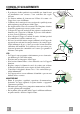
CONSIGLI E SUGGERIMENTI INSTALLAZIONE • Il produttore declina qualsiasi responsabilità per danni dovuti ad installazione non corretta o non conforme alle regole dell’arte. • La distanza minima di sicurezza tra il Piano di cottura e la Cappa deve essere di 650 mm. • Verificare che la tensione di rete corrisponda a quella riportata nella targhetta posta all’interno della Cappa. • Per Apparecchi in Classe Ia accertarsi che l’impianto elettrico domestico garantisca un corretto scarico a terra.
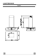
CARATTERISTICHE Ingombro IT 8 8
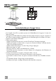
21 Componenti Rif. 1 2 2.1 2.2 7.1 Q.tà 1 1 1 1 1 7.1a 7.1b 10 10a 15 24 25 1 1 1 1 1 1 2 Componenti di Prodotto Corpo Cappa completo di: Comandi, Luce, Filtri Camino telescopico formato da: Camino superiore Camino inferiore Traliccio telescopico completo di Aspiratore, formato da: Traliccio superiore Traliccio inferiore Flangia ø 150 Flangia con valvola ø 150 mm Raccordo Uscita Aria Scatola connessioni Fascette stringitubo 23 11 22 12h 7.1a 15 12g 7.1 10 7.1b 9 25 12c 2.1 2 Rif.
INSTALLAZIONE Foratura Soffitto/Mensola e Fissaggio Traliccio FORATURA SOFFITTO/MENSOLA • Con l’ausilio di un Filo a piombo riportare sul Soffitto/Mensola di supporto il centro del Piano di Cottura. • Appoggiare al Soffitto/Mensola la Dima di Foratura 21 in dotazione, facendo coincidere il suo centro al centro proiettato e allineando gli assi della Dima agli assi del Piano di Cottura. • Segnare i centri dei Fori della Dima.
Fissaggio Traliccio • Svitare le due viti che fissano il camino inferiore e sfilarlo dal traliccio (dalla parte inferiore). • Svitare le due viti che fissano il camino superiore e sfilarlo dal traliccio (dalla parte superiore).
Uscita aria Versione Filtrante • Fissare il Raccordo 15 al traliccio utilizzando le 4 Viti in dotazione. • Incastrare la flangia 10 nell’apposito foro inferiore del Raccordo 15. • Collegare l’uscita aria della cappa con la flangia posta sotto al raccordo per mezzo di un tubo rigido o flessibile ø 150mm , la cui scelta è lasciata all’installatore Montaggio Camino e Fissaggio Corpo Cappa • Posizionare il Camino superiore e fissare nella parte superiore al Traliccio con 2 Viti 12c (2,9 x 6,5) in dotazione.
USO T1 T2 T4 T3 T5 L Quadro Comandi T1 TASTO ON/OFF Motore T2 T3 T4 Velocità Velocità + Velocità intensiva T5 Delay L Luci IT FUNZIONI Attiva e arresta il motore d’aspirazione. Sul display viene visualizzato lo step di velocità precedentemente impostata. Decrementa la velocità del motore: V3 →V2 → V1 Incrementa la velocità del motore: V1→V2→ V3 Attiva la velocità intensiva da qualsiasi velocità o da motore spento.Per disinserirla basta premere di nuovo lo stesso tasto o spegnere il motore.
MANUTENZIONE Filtri antigrasso PULIZIA FILTRI ANTIGRASSO METALLICI AUTOPORTANTI • Sono lavabili anche in lavastoviglie, e necessitano di essere lavati ogni 2 mesi circa di utilizzo o più frequentemente, per un uso particolarmente intenso. • Togliere i Filtri uno alla volta,sostenendoli con una mano mentre con l’altra si tira la leva verso il basso. • Lavare i Filtri evitando di piegarli, e lasciarli asciugare prima di rimontarli.
RECOMMENDATIONS AND SUGGESTIONS INSTALLATION • The manufacturer will not be held liable for any damages resulting from incorrect or improper installation. • The minimum safety distance between the cooker top and the extractor hood is 650 mm. • Check that the mains voltage corresponds to that indicated on the rating plate fixed to the inside of the hood. • For Class I appliances, check that the domestic power supply guarantees adequate earthing.
CHARACTERISTICS Dimensions EN 1 16 6
21 Components Ref. 1 2 2.1 2.2 7.1 7.1a 7.1b 10 10a 15 24 25 Q.ty Product Components 1 Hood Body, complete with: Controls, Light, Blower, Filters 1 Telescopic Chimney comprising: 1 Upper Section 1 Lower Section 1 Telescopic frame complete with extractor, consisting of: 1 Upper frame 1 Lower frame 1 Flange ø 150 1 Dumper ø 150mm 1 Air Outlet Connection 1 Junction box 2 Pipe clamps 23 11 22 12h 7.1a 15 12g 7.1 10 7.1b 9 25 12c 2.1 2 Ref. 11 12c 12e 12f 12g 12h 21 22 23 Q.
INSTALLATION Drilling the Ceiling/shelf and fixing the frame DRILLING THE CEILING/SHELF • Use a plumb line to mark the centre of the hob on the ceiling/support shelf. • Place the drilling template 21 provided on the ceiling/support shelf, making sure that the template is in the correct position by lining up the axes of the template with those of the hob. • Mark the centres of the holes in the template.
FIXING THE frame • Loosen the two screws fastening the lower chimney and remove this from the lower frame. • Loosen the two screws fastening the upper chimney and remove this from the upper frame. If you wish to adjust the height of the frame, proceed as follows: • Unfasten the eight metric screws joining the two columns, located at the sides of the frame. • Adjust the frame to the height required, then replace all the screws removed as above.
Recirculation version air outlet 15 • Fix the connection 15 to the frame using the 4 screws provided. • Fix the flange 10 to the lower opening of the connection 15. • Connect the hood air outlet to the flange in the lower part of the junction using a rigid or flexible ø 150 tube (by installer’s choice). Flue assembly - Mounting the hood body • Position the upper chimney section and fix the upper part to the frame using the 2 screws 12c (2,9 x 6,5) provided.
USE T1 T2 T4 T3 T5 L Control panel TOUCH CONTROL T1 ON/OFF Motor T2 T3 T4 Speed Speed + Intensive speed T5 Delay L Lighting EN FUNCTION Switches the hood motor on and off. The latest selected speed appears on the display. Decreases the suction speed: V3 → V2 → V1 Increases the suction speed: V1 → V2 → V3 Activates the intensive speed from any previously selected speed. The intensive speed can be activated even when the motor is OFF.
MAINTENANCE Grease filters CLEANING METAL SELF- SUPPORTING GREASE FILTERS • The filters must be cleaned every 2 months of operation, or more frequently for particularly heavy usage, and can be washed in a dishwasher. • Remove the filters one at a time holding them up with one hand and pulling the handle downwards with the other hand at the same time. • Wash the filters, taking care not to bend them. Allow them to dry before refitting.
CONSEILS ET SUGGESTIONS INSTALLATION • Le fabricant décline toute responsabilité en cas de dommage dû à une installation non correcte ou non conforme aux règles de l’art. • La distance minimale de sécurité entre le plan de cuisson et la hotte doit être de 650 mm au moins. • Vérifier que la tension du secteur correspond à la valeur qui figure sur la plaquette apposée à l’intérieur de la hotte.
CARACTERISTIQUES Encombrement FR 2 24 4
21 Composants Réf. 1 2 2.1 2.2 7.1 7.1a 7.1b 10 10a 15 24 25 Q.té 1 1 1 1 1 1 1 1 1 1 1 2 Composants de Produit Corps Hotte équipé de: Comandes, Lumière, Filtres Cheminée Télescopique formée de : Cheminée Supérieure Cheminée Inférieure Treillis télescopique avec Aspirateur, formé par: Treillis supérieur Treillis inférieur Flasque ø 150 Buse avec clapet ø 150 Raccord Sortie Air Boîte connexions Colliers de serrage serre-tube Réf. 11 12c 12e 12f 12g 12h 21 22 23 Q.
INSTALLATION Perçage Plafond/Étagère et Fixation Treillis PERÇAGE PLAFOND/ETAGERE • À l’aide d’un Fil à plomb, reporter sur le Plafond/Étagère de support le centre du Plan de Cuisson. • Poser contre le Plafond/Étagère le Gabarit de Perçage 21 fourni avec l’appareil, en faisant coïncider son centre avec le centre projeté et en alignant les axes du Gabarit avec les axes du Plan de Cuisson. • Marquer les centres des Trous du Gabarit.
FiXATION TREILLIS • Dévisser les deux vis qui fixent la cheminée inférieure et sortir cette dernière du treillis (depuis la partie inférieure). • Dévisser les deux vis qui fixent la cheminée supérieure et sortir cette dernière du treillis (depuis la partie supérieure). Si l’on souhaite régler la hauteur du treillis, effectuer les opérations suivantes: • Dévisser les huit vis métriques qui unissent les deux colonnes, qui se trouvent sur les côtés du treillis.
Sortie air version Filtrante 15 • Fixer le raccord 15 au Treillis à l’aide des 4 Vis fournies avec l’appareil. • Bloquer la bride 10 dans le trou inférieur de le raccord 15. • Joindre la sortie d’air de la hotte avec la bride placée sous la rallonge par un tuyau rigide ou flexible ø 150 ( le choix est de l’installateur).
UTILISATION T1 T2 T3 T4 T5 L Tableau des commandes T1 TOUCHE ON/OFF Moteur T2 T3 T4 Vitesse Vitesse + Vitesse intensive T5 Delay L Éclairage FR FONCTIONS Actionne et arrête le moteur d’aspiration. Sur l’afficheur est visualisé le pas de la vitesse précédemment sélectionnée. Réduit la vitesse du moteur: V3 → V2 → V1 Augmente la vitesse du moteur: V1 → V2 → V3 Actionne la vitesse intensive en partant d’une vitesse quelconque ou lorsque le moteur est éteint.
ENTRETIEN Filtres anti-graisse NETTOYAGE FILTRES ANTI-GRAISSE METALLIQUES AUTOPORTEURS • Lavables au lave-vaisselle, ils doivent être lavés environ tous les 2 mois d’emploi ou plus fréquemment en cas d’emploi particulièrement intense. • Enlevez les filtres l’un après l’autre en les soutenant avec une main et en tirant en même temps la poignée vers le bas avec l’autre main. • Laver les filtres en évitant de les plier et les laisser sécher avant de les remonter.
EMPFEHLUNGEN UND HINWEISE MONTAGE • Der Hersteller haftet nicht für Schäden, die auf eine fehlerhafte und unsachgemäße Montage zurückzuführen sind. • Der minimale Sicherheitsabstand zwischen Kochmulde und Haube muss 650 mm betragen. • Prüfen, ob die Netzspannung mit dem Wert auf dem im Haubeninneren angebrachten Schild übereinstimmt. • Bei Geräten der Klasse I ist sicherzustellen, dass die elektrische Anlage des Wohnhauses über eine vorschriftsmäßige Erdung verfügt.
CHARAKTERISTIKEN Platzbedarf DE 3 32 2
21 Komponenten Pos. 1 2 2.1 2.2 7.1 7.1a 7.1b 10 10a 15 24 25 St. 1 1 1 1 1 1 1 1 1 1 1 2 Produktkomponenten Haubenkörper mit Schaltern, Teleskopkamin bestehend aus: oberer Kaminteil unterer Kaminteil Teleskopgerüst komplett mit Gebläse, bestehend aus: oberer Gerüstteil unterer Gerüstteil Flansch ø 150 Flansch mit Ruckstauklappe ø 150 Luftaustritt-Anschlussstück Verbindungsdose Rohrschellen Pos. 11 12c 12e 12f 12g 12h 21 22 23 St.
MONTAGE Bohren der Decke/Trägerplatte und Montage des Teleskopgerüsts BOHREN DER DECKE/TRAGERPLATTE • Mit Hilfe eines Lots den Kochmulden-Mittelpunkt an der Decke oder Trägerplatte ermitteln und kennzeichnen. • Die mitgelieferte Bohrschablone 21 so auf die Decke/Trägerplatte legen, dass die Schablonenmitte mit dem gekennzeichneten Mittelpunkt übereinstimmt und die Schablonenseiten auf die Seiten der Kochmulde ausrichten. • Die Mitte der Schablonenbohrungen kennzeichnen.
MONTAGE DES TELESKOPGERÜSTS • Die beiden Schrauben lösen, die den unteren Kaminteil fixieren und diesen aus dem Gerüst ziehen (an der Unterseite) • Die beiden Schrauben lösen, die den oberen Kaminteil fixieren und diesen aus dem Gerüst ziehen (an der Oberseite). Für eine eventuelle Regulierung der Gerüsthöhe folgendermaßen vorgehen: • Die acht Stellschrauben an den Gerüstseiten, die die beiden Säulen vereinen, lösen. • Den oberen Kaminteil von oben einfügen und frei auf dem Gerüst lassen.
Anschluss in Umluftversion • Der Anschluß 15 an das Teleskopgerüst mit den 4 beiliegenden Schrauben befestigen. • Den Flansch 10 an die untere Bohrung des Anschluß 15 anbringen. • Den Haubenluftaustritt mit Hilfe eines Rohres oder Schlauches Ø 150 (die Wahl bleibt dem Installateur überlassen) mit dem Flansch, der sich unter dem Umlenkteil befindet, verbinden.
BEDIENUNG T1 T2 TASTE T1 Motor ON/OFF T3 T4 T5 L Bedienfeld FUNKTIONEN Schaltet den Gebläsemotor ein und aus. Auf dem Display wird die zuvor eingestellte Geschwindigkeitsstufe angezeigt. T2 Geschwindigkeit - Erhöht die Geschwindigkeit des Motors: V3 → V2 → V1 T3 Geschwindigkeit + Verringert die Geschwindigkeit des Motors: V1 → V2 → V3 T4 Intensivstufe Aktiviert die Intensivstufe von jeder Geschwindigkeitsstufe aus oder bei ausgeschaltetem Motor.
WARTUNG Fettfilter SELBSTTRAGENDER METALLFETTFILTER REINIGUNG • Sie müssen nach 2-monatigem Betrieb bzw. bei starkem Einsatz auch häufiger gereinigt werden, was im Geschirrspüler möglich ist. • Einen Filter nach dem anderen entfernen. Halten Sie den Filter mit einer Hand fest und ziehen Sie den Griff mit der anderen Hand gleichzeitig nach unten. • Die Filter reinigen (darauf achten, sie nicht zu verbiegen) und vor der Remontage trocknen lassen.
TAVSIYELER VE ÖNERILER MONTAJ • Yalnιş veya eksik montajdan doğan herhangi bir zararιn sorumluluğu üreticiye ait değildir. • Davlumbaz ile pişirici cihazιn ocak kιsmι arasιndaki minimum güvenlik mesafesi 650 mm.dir. • Besleme voltajιnιn, davlumbaz içerisine yerleştirilen bilgi etiketinde belirtilenle aynι olup olmadιğιnι kontrol edin. • Sιnιf I elektrikli aletleri için, güç kaynağιnιn yeterli topraklamayι sağlayιp sağlamadιğιnι kontrol edin.
ÖZELLIKLER Boyutlar TR 4 40 0
Parçalar 21 Ref. 1 Adet Ürün Parçaları 1 Şunlardan oluşan Davlumbaz Gövdesi: Kumandalar, Lamba, Filtreler 2 1 Şunlardan oluşan Teleskopik Baca: 2.1 1 Üst Baca 2.2 1 Alt Baca 7.1 1 Şunlardan oluşan Aspiratörlü teleskopik kafes: 7.1a 1 Üst kafes 7.1b 1 Alt kafes 10 1 Flanş ø 150 10a 1 Valfli flanş ø 150 mm 15 1 Hava Çıkışı Rakoru 24 1 Bağlantı kutusu 25 2 Boru kelepçeleri 23 11 22 12h 7.1a 15 12g 7.1 10 7.1b 9 25 12c 2.1 Ref.
MONTAJ Tavan / Konsol delme işlemi ve Kafesin Sabitlenmesi TAVANIN YADA KONSOLUN DELİNMESİ • Bir şakül yardımıyla tavana ya da destek konsolüne pişirme tezgahının merkezini işaretleyiniz. • Tavana veya konsola donanımla birlikte verilen delik delme şablonunu (21) dayayınız ve bunun merkeziyle işaretlenen merkezi birbirine çakıştırınız. Yani şablonun ekseni ile pişirme tezgahı ekseni bir hizaya gelmiş olsun. • Delik delme şablonuyla delikleri duvara işaretleyiniz.
Kafesin Sabitlenmesi • Alt bacayı sabitleyen iki adet vidayı söküp kafesten çıkarınız (alt kısımdan). • Üst bacayı sabitleyen iki adet vidayı söküp kafesten çıkarınız (üst kısımdan).
Filtreli Model Hava Çıkışı • Rakoru cihaz donanımındaki 4 adet Vida ile kafese sabitleyiniz. • Flanşı 10 Rakorun 15 bu işe ayrılmış alt deliğine geçiriniz. • Davlumbazın flanşlı hava çıkışını, tercihi monitöre kalmış sert ya da rijit 150 mm çapında bir boru ile rakora bağlayınız. Baca Montajı ve Davlumbaz Gövdesinin Sabitlenmesi 15 10 12c • Üst Bacayı yerleştiriniz ve cihaz donanımındaki 2 adet vidayı 12c (2,9 x 6,5) kullanarak yukarı kısımdan Kafese sabitleyiniz.
KULLANIM T1 T2 T4 T3 T5 L Kumanda Tablosu T1 TUŞ Motor ON/OFF T2 T3 T4 Hız Hız + Yoğun Hız T5 Delay L Lambalar TR FONKSİYONLARI Aspiratör motorunu açar-kapatır. Ekranda daha önce ayarlanmış olan hız kademesi görüntüye gelir. Motorun hızını kademeli olarak azaltır: V3 → V2 → V1 Motorun hızını kademeli olarak arttırır: V1 → V2 → V3 Herhangi bir hızdayken, ya da motor kapalı iken yoğun hızı devreye alır. Devreden çıkarmak için aynı tuşa yeniden basmak ve motoru kapatmak gerekir.
BAKIM Yağ tutucu filtreler • • • • METALİK YAĞ TUTUCU FİLTRELERİN TEMİZLENMESİ Bu filtreler bulaşık makinasında da yıkanabilir ve normal kullanıldıklarında iki ayda bir, yoğun kullanım halinde ise daha sıkça yıkanmalarıı gereklidir. Filtreleri teker teker çıkarınız ve bunu yaparken kolu aşağı doğru çektiğiniz sırada diğer elinizle filtreleri tutunuz. Filtreleri yıkarken eğip katlamayınız, tekrar monte etmeden önce de kurutunuz. Monte ederken kulpun görünen dış tarafa doğru gelmesine dikkat ediniz.
Dir. 89/336/CEE 73/23/CEE 93/68/CEE Il simbolo sul prodotto o sulla confezione indica che il prodotto non deve essere considerato come un normale rifiuto domestico, ma deve essere portato nel punto di raccolta appropriato per il riciclaggio di apparecchiature elettriche ed elettroniche. Provvedendo a smaltire questo prodotto in modo appropriato, si contribuisce a evitare potenziali conseguenze negative per l’ambiente e per la salute, che potrebbero derivare da uno smaltimento inadeguato del prodotto.