IT Istruzioni per l’uso e l’installazione Cappa GB Instructions for use and installation FR Mode d’emploi et installation DE Bedienungsanleitung und Einrichtung TR Kullanım ve montaj talimatları Cooker Hood Hotte de Cuisine Dunstabzugshaube Davlumbaz FTC 622 FTC 922
Libretto di Istruzioni INDICE CONSIGLI E SUGGERIMENTI ..............................................................................................................................................7 CARATTERISTICHE ..............................................................................................................................................................8 INSTALLAZIONE.............................................................................................................................
Instructions Manual INDEX RECOMMENDATIONS AND SUGGESTIONS ....................................................................................................................13 CHARACTERISTICS............................................................................................................................................................14 INSTALLATION ....................................................................................................................................................
Manuel d’Instructions SOMMAIRE CONSEILS ET SUGGESTIONS ..........................................................................................................................................19 CARACTERISTIQUES .........................................................................................................................................................20 INSTALLATION ..................................................................................................................................
Bedienungsanleitung INHALTSVERZEICHNIS EMPFEHLUNGEN UND HINWEISE....................................................................................................................................25 CHARAKTERISTIKEN..........................................................................................................................................................26 MONTAGE.....................................................................................................................................
Kullanim Kilavuku IÇERIKLER TAVSIYELER VE ÖNERILER ..............................................................................................................................................31 ÖZELLIKLER ........................................................................................................................................................................32 MONTAJ ...............................................................................................................................
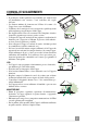
CONSIGLI E SUGGERIMENTI INSTALLAZIONE • Il produttore declina qualsiasi responsabilità per danni dovuti ad installazione non corretta o non conforme alle regole dell’arte. • La distanza minima di sicurezza tra il Piano di cottura e la Cappa deve essere di 650 mm. • Verificare che la tensione di rete corrisponda a quella riportata nella targhetta posta all’interno della Cappa. • Per Apparecchi in Classe Ia accertarsi che l’impianto elettrico domestico garantisca un corretto scarico a terra.
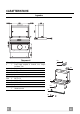
CARATTERISTICHE Ingombro Componenti Rif. 1 8 10a 20 Q.tà Componenti di Prodotto 1 Corpo Cappa completo di: Comandi, Luce, Gruppo Ventilatore, Filtri 1 Griglia direzionata uscita aria 1 Flangia ø 120 1 Profilo chiusura Rif. 12a 12e 12f Q.tà 4 2 3 12e 8 10a Componenti di Installazione Viti 3,5 x 16 Viti 2,9 x 12,7 Viti 2,9 x 9,5 Q.
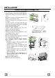
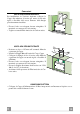
INSTALLAZIONE Foratura Piano di supporto e Montaggio Cappa • La Cappa può essere installata direttamente sul piano inferiore dei Pensili (650 mm min. dal Piano di Cottura) con i Supporti laterali a scatto. • Praticare un incasso sul piano inferiore del Pensile, come indicato. (fig.1) • Inserire la flangia nel foro superiore di scarico. (fig.2) • Avvitare il profilo di chiusura 20 alla parte posteriore della cappa utilizzando le viti 12f (2,9 x 9,5) in dotazione. (fig.3) • Aprire il carrello aspirante.
Connessioni USCITA ARIA VERSIONE ASPIRANTE Per installazione in Versione Aspirante collegare la Cappa alla tubazione di uscita per mezzo di un tubo rigido o flessibile dello stesso diametro della flangia precedentemente installata • Fissare il tubo con adeguate fascette stringitubo. Il materiale occorrente non è in dotazione. • Togliere eventuali Filtri Antiodore al Carbone attivo. USCITA ARIA VERSIONE FILTRANTE 12e • Praticare un foro ø 125 mm sull’eventuale Mensola soprastante la Cappa.
USO L M Le varie funzioni vengono attivate automaticamente con l’estrazione del carrello. Per spegnere le funzioni impostate sarà sufficiente richiudere il carrello. TASTO FUNZIONE L Luci Accende e spegne l’Impianto di Illuminazione. M Motore Accende e spegne il motore Aspirazione. 1. Velocità minima, adatta ad un ricambio d’aria continuo particolarmente silenzioso,in presenza di pochi vapori di cottura. 2.
MANUTENZIONE Filtri antigrasso PULIZIA FILTRI ANTIGRASSO METALLICI AUTOPORTANTI • Sono lavabili anche in lavastoviglie, e necessitano di essere lavati ogni 2 mesi circa di utilizzo o più frequentemente, per un uso particolarmente intenso. • Estrarre il carrello aspirante. • Togliere i Filtri uno alla volta, agendo sugli appositi agganci. • Lavare i Filtri evitando di piegarli, e lasciarli asciugare prima di rimontarli.
RECOMMENDATIONS AND SUGGESTIONS INSTALLATION • The manufacturer will not be held liable for any damages resulting from incorrect or improper installation. • The minimum safety distance between the cooker top and the extractor hood is 650 mm. • Check that the mains voltage corresponds to that indicated on the rating plate fixed to the inside of the hood. • For Class I appliances, check that the domestic power supply guarantees adequate earthing.
CHARACTERISTICS Dimensions Components Ref. 1 8 10a 20 Q.ty Product Components 1 Hood Body, complete with: Controls, Light, Blower, Filters 1 Directional Air Outlet grille 1 Flange ø 120 mm 1 Closing element Ref. 12a 12e 12f Q.ty 4 2 3 12e 8 10a Installation Components Screws 3,5 x 16 Screws 2,9 x 12,7 Screws 2,9 x 9,5 1 12a Q.
INSTALLATION Drilling the Support surface and Fitting the Hood • The Hood can be fitted directly on the lower surface of the Wall Units (650 mm min. above the Cooker Top) using the snapon Side Supports. • Make an opening on the lower surface of the Wall Unit, as indicated. (fig.1) • Choose the correct flange measure basing on the air outlet diameter and insert it to the upper air outlet opening. (fig.2) • Screw the closing profile 20 onto the rear part of the hood, using the screws 12f (2.9 x 9.5) provided.
Connections DUCTING VERSION AIR EXHAUST SYSTEM When installing the hood in ducting version, a rigid or a flexible pipe with the diameter corresponding to the flange diameter is used in order to connect the hood to the air outlet piping. • Fix the pipe with an adequate quantity of clamps (not supplied). • Remove possible charcoal filters. pipe RECIRCULATION VERSION AIR OUTLET 12e • Cut a hole ø 125 mm in any shelf that may be positioned over the hood. • Insert the flange 10a on the hood body outlet.
USE L M By pulling out the sliding panel it is possible to automatically activate all the hood functions. By simply closing the sliding panel all the functions are switched off. SWITCH FUNCTIONS L Light Switches the lighting system on and off M Motor Switches the extractor motor on and off 1. Low speed, used for a continuous and silent air change in the presence of light cooking vapour. 2.
MAINTENANCE Grease filters CLEANING METAL CASSETTE GREASE FILTERS • The filters must be cleaned every 2 months, or more frequently in case of particularly heavy use of the hood. Filters can be washed in a dishwasher. • Pull out the sliding suction panel. • Remove the filters one by one, after having disconnected the relative fastening elements. • Wash the filters, taking care not to bend them. Let them get dry before refitting them.
CONSEILS ET SUGGESTIONS INSTALLATION • Le fabricant décline toute responsabilité en cas de dommage dû à une installation non correcte ou non conforme aux règles de l’art. • La distance minimale de sécurité entre le plan de cuisson et la hotte doit être de 650 mm au moins. • Vérifier que la tension du secteur correspond à la valeur qui figure sur la plaquette apposée à l’intérieur de la hotte.
CARACTERISTIQUES Encombrement Composants Réf. 1 8 10a 20 Q.té Composants de Produit 1 Corps Hotte équipé de: Commandes, Lumière, Groupe Ventilateur, Filtres 1 Grille orientée Sortie de l’Air 1 Flasque ø 120 mm 1 Profil fermeture Réf. 12a 12e 12f Q.té 4 2 3 12e 8 10a Composants pour l ’installation Vis 3,5 x 16 Vis 2,9 x 12,7 Vis 2,9 x 9,5 Q.
INSTALLATION Perçage du Plan de support et Montage de la Hotte • Il est possible d’installer la Hotte directement sur le plan inférieur des Armoires murales (650 mm. min. par rapport aux Plaques de Cuisson), à l’aide des Supports latéraux par encliquetage. • Percer une ouverture (emboîtage) sur le plan inférieur de l’Armoire murale, comme indiqué. (fig.1) • Insérer la flasque correcte dans le trou supérieur de sortie de l’air. (fig.
Branchements SORTIE AIR VERSION ASPIRANTE En cas d’installation en version aspirante, brancher la hotte à la tuyauterie de sortie utilisant un tube rigide ou flexible avec le même diamètre de la flasque précédemment installée. • Fixer le tube par des colliers appropriés. Le matériau nécessaire n’est pas fourni. • Retirer les éventuels filtres anti-odeur au charbon actif. SORTIE AIR VERSION FILTRANTE 12e • Percer un trou de ø 125 mm. sur l’éventuelle Tablette qui se trouve au-dessus de la Hotte.
UTILISATION L M Les différentes fonctions de la hotte sont activées automatiquement avec l’ouverture du tiroir. Pour arrêter les fonctions sélectionnées il suffit de fermer le tiroir. TOUCHE FUNCTIONS L Lumières Allume et éteint l’éclairage. M Moteur Allume et éteint le moteur aspiration 1. Vitesse minimale, pour un rechange d’air permanent particulièrement silencieux en cas de faibles vapeurs de cuisson. 2.
ENTRETIEN Filtres anti-graisse NETTOYAGE DES FILTRES ANTI-GRAISSE MÉTALLIQUES AUTOPORTEURS • Les filtres peuvent être également lavés au lave-vaisselle; il faut les laver tous les 2 mois d’emploi environ, ou bien plus souvent, en cas d’emploi particulièrement intense. • Sortir le chariot aspirant. • Retirer un Filtre à la fois, en intervenant sur les crochets spécialement prévus.
EMPFEHLUNGEN UND HINWEISE MONTAGE • Der Hersteller haftet nicht für Schäden, die auf eine fehlerhafte und unsachgemäße Montage zurückzuführen sind. • Der minimale Sicherheitsabstand zwischen Kochmulde und Haube muss 650 mm betragen. • Prüfen, ob die Netzspannung mit dem Wert auf dem im Haubeninneren angebrachten Schild übereinstimmt. • Bei Geräten der Klasse I ist sicherzustellen, dass die elektrische Anlage des Wohnhauses über eine vorschriftsmäßige Erdung verfügt.
CHARAKTERISTIKEN Platzbedarf Komponenten Pos. 1 St. 1 8 10a 20 1 1 1 Produktkomponenten Haubenkörper mit Schaltern, Beleuchtung, Gebläsegruppe, Filter Luftleitgitter Luftaustritt Flansch ø 120 mm Abdeckprofil Pos. 12a 12e 12e St. 4 2 3 Montagekomponenten Schrauben 3,5 x 16 Schrauben 2,9 x 12,7 Schrauben 2,9 x 9,5 St.
MONTAGE Bohren der Trägerplatte und Montage der Dunstabzugshaube • Die Haube kann direkt an der Unterseite der Hängeschränke (mindestens 650 mm von der Kochmulde entfernt) mit seitlichen Schnapphalterungen fixiert werden. • An der Unterseite des Hängeschranks, wie in der Abbildung gezeigt, eine Öffnung anbringen. (Abb.1) • Abluftstutzen in die obere Luftaustrittsöffnung einstecken. (Abb.2) • Das Abschlussprofil 20 an der Rückseite der Haube mit den beiliegenden Schrauben 12f (2,9x9,5) fixieren. (Abb.
Anschlüsse ANSCHLUSS IN ABLUFTVERSION Für die Installation in Abluftversion die Haube mit Hilfe eines Rohres oder Schlauches vom selben Durchmesser wie der zuvor installierte Flansch an die Auslassleitung anschließen. • Das Rohr mit geeigneten Rohrschellen fixieren. Das hierzu erforderliche Material wird nicht mitgeliefert. • Eventuell vorhandene Aktivkohlefilter entnehmen. ANSCHLUSS IN UMLUFTVERSION • In das eventuell über der Haube vorhandene Bord ein Loch ø 125 mm bohren.
BEDIENUNG L M Die verschiedenen Funktionen werden automatisch beim Öffnen des Paneels eingeschaltet. Um die Funktionen wieder auszuschalten, das Paneel wieder schließen. SCHALTER FUNKTION L Beleucht Schaltet die Beleuchtung ein und aus M Motor Schaltet den Gebläsemotor ein und aus 1. geringste Gebläsestufe, diese Stufe ist für einen ständigen und besonders leisen Luftaustausch bei geringer Kochdunstentwicklung geeignet. 2.
WARTUNG Fettfilter REINIGUNG DER SELBSTTRAGENDEN METALLFETTFILTER • Die Filter können auch im Geschirrspüler gereinigt werden und müssen nach zwei Monaten Betriebszeit oder, bei besonders intensiver Nutzung, öfter gereinigt werden. • Den Ansaugschlitten herausziehen. • Die entsprechenden Haken lösen und die Filter einzeln herausnehmen. • Die Filter reinigen und vor dem Wiedereinsetzen trocknen lassen, dabei nicht knicken.
TAVSIYELER VE ÖNERILER MONTAJ • Yalnιş veya eksik montajdan doğan herhangi bir zararιn sorumluluğu üreticiye ait değildir. • Davlumbaz ile pişirici cihazιn ocak kιsmι arasιndaki minimum güvenlik mesafesi 650 mm.dir. • Besleme voltajιnιn, davlumbaz içerisine yerleştirilen bilgi etiketinde belirtilenle aynι olup olmadιğιnι kontrol edin. • Sιnιf I elektrikli aletleri için, güç kaynağιnιn yeterli topraklamayι sağlayιp sağlamadιğιnι kontrol edin.
ÖZELLIKLER Boyutlar Bileşenler Ref. 1 8 10a 20 12e Adet Ürün Bileşenleri 1 Kumandaları, Işığı, Vantilatör Grubu ve Filtreleri ile komple Baca Gövdesi 1 Hava tahliye ızgarası 1 Flanş ø 120 1 Kapak profili 8 10a Ref..
MONTAJ Destek Düzlemi Delme Planı ve Baca Montajı • Yan kilit destekleri aracılığı ile bacanın doğrudan asma dolapların alt kısmına monte edilmesi mümkündür (ocak seviyesinin en az 650 mm yukarısında). • Gösterildiği gibi, dolabın alt kısmına bir alan açılır (Şekil 1). • Flanşı üst tahliye deliğine yerleştirin (Şekil 2). • Kapak profilini 20 12f vidalarını (2,9 x 9,5) kullanarak bacanın arka kısmına vidalayınız (Şekil 3). • Emme grubunu açın.
Bağlantılar EMME MODELİ HAVA TAHLİYESİ Emme modelini monte etmek için bacayı tahliye bacasına bağlayın. Ara parça olarak, genişliği önceden monte edilen flanşın çapı ile aynı olan esnek veya esnek olmayan bir hortum kullanın. • Hortumu uygun kelepçeler aracılığı ile sıkın. Gereken malzemeler dahil değildir. • Aktif karbonlu koku önleyici filtreler var ise bunları çıkarın. FİLTRE MODELİNDE HAVA TAHLİYESİ • Bacanın üstünde yer alan olası rafa 125 mm çapında bir delik açın.
KULLANIM L M Şaryonun dışarıya doğru kaydırılması ile farklı fonksiyonlar aktif hale gelmektedir. Bunların kapatılması için şaryonun yere kaydırılması yeterli olacaktır. DÜĞME İŞLEVİ L Işıklar Işıklandırma sistemini açar ve kapatır. M Motor Havalandırma motorunu açar ve kapatır. 1. Minimum hız; sessiz bir şekilde sürekli hava değişimini sağlar; az dumanlı durumlarda kullanılır. 2.
BAKIM Yağ filtreleri • • • • • • MONTELİ METAL YAĞ FİLTRELERİNİN TEMİZLİĞİ Bulaşık makinesinde yıkanabilirler, 2 ayda bir veya özellikle yoğun kullanım söz konusu ise daha sık yıkanmalıdırlar. Emme arabasını çıkartın. Kancalarına bastırmak sureti ile filtreleri teker teker çıkartın. Filtreleri katlamadan yıkayın ve monte etmeden önce kurutun. (Zamanla filtre yüzeyinde meydana gelebilecek renk değişikliği filtrenin etkinliğinde kesinlikle bir azalmaya neden olmaz.
Dir. 89/336/CEE 73/23/CEE 93/68/CEE Il simbolo sul prodotto o sulla confezione indica che il prodotto non deve essere considerato come un normale rifiuto domestico, ma deve essere portato nel punto di raccolta appropriato per il riciclaggio di apparecchiature elettriche ed elettroniche. Provvedendo a smaltire questo prodotto in modo appropriato, si contribuisce a evitare potenziali conseguenze negative per l’ambiente e per la salute, che potrebbero derivare da uno smaltimento inadeguato del prodotto.