Colibri Tank Monitoring System CL6 Series Set-Up and Operator’s Guide Franklin Fueling Systems • 3760 Marsh Rd. • Madison, WI 53718 USA Tel: +1 608 838 8786 • 800 225 9787 • Fax: +1 608 838 6433 • www.franklinfueling.
Important Safety Messages This equipment is installed close to gasoline and diesel fuel. Working in such a hazardous environment presents a risk of severe injury or death if these instructions and standard industry practices are not followed. Read and follow all instructions thoroughly before installing or working on this, or any other related, equipment.
Contents Important Safety Messages.............................................................................................2 Basic Console Operation.................................................................................................3 LCD Layout.............................................................................................................................. 3 Set up Preferences......................................................................................................
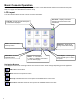
Basic Console Operation The console can be operated through the LCD touch screen or the Web Browser Interface via a Personal Computer. Refer to to page 16 for Web Browser Interface setup. LCD Layout The LCD interface allows the user to enter on-screen information. Path Bar – Shows the path / description of information displayed. User Role – Displays and allows changing the access level of the current user Home – Goes to the home summary screen. Main Menu – Access the Application Menu.
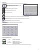
Data Entry If you are prompted to enter information, a keypad and edit buttons will be displayed. Character Selection: Selects between upper case letters, lower case letters and numerals. Backspace: Deletes the previous character. Clear: Deletes data from the entry line. Enter: Accepts the choice. Cancel: Returns to the application and no changes will be made to console settings. Restore Default: This will restore the original settings programmed into the console.
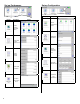
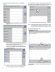
Set up Preferences Set up Configuration Display Display Description Description Values Choose passwords for access Choose language for console menus.
Allows technicians access to diagnostic functions* Display Description Values View relay state and test operation (read screen caution notice)! Lists detail about the Console * Call FFS Tech Support for the password Lists System Parameters Display Lists options enabled Description Values Restore factory default settings Will erase all archived data Display Description To Silence the annunciator To print or e-mail a test page Values Will reboot system Re-calibrates screen 7
Entering Setup Always enter information starting from the top of the menu. Later menus use this information. Note that the tables are formatted to correspond to the Web Browser Interface. Information shown is also valid for the LCD touch screen. [Setup] / System ID Parameter Name Site Name Web UI URL ID Line 1 ID Line 2 ID Line 3 ID Line 4 ID Line 5 Parameter Value (Site Name) (http://localhost/tsa) (blank) (blank) (blank) (blank) (blank) Description Name of site. URL address of site.
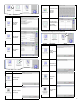
[Setup] / Dispenser Interface Note: The Dispenser Interface allows the console to read dispensing information and requires the TS-TRAC option. Dispenser information is sent through the Serial Port. Parameter Name Grades Parameter Name Parameter Value Description Number of grades (0) The number and name of products used at the site. (0-32) Fueling Points Number of fueling points Hoses Number of hoses (0) Anywhere on site where a vehicle can get fueled.
Select each grade and assign a name (i.e. Unleaded Regular). 4. Enter the number of fueling points. In this example there are 4. This will allow the console to automatically program hose information (grade association and position) for the Fueling points based on information received from the D-box. 7. Follow the instructions on the screen. Note: Dispensing small amounts of fuel from each hose is required before copying the information to other fueling points that have the same number of hoses.
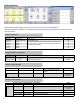
This action will copy the grade association and position information to the other Fueling points. Next Screen [Setup] / Fuel Management System Parameter Name Ullage Percent Delivery Delay Correction Temperature Parameter Value (95) (15 min) (15.50 °C) Description Percent of tank level used to calculate space left. Time after delivery when increase is reported. Value 70-100 % 1 - 240 min. Product temperature correction. -15 to 37.78 °C Choose Volume or Level.
[Setup] / Fuel Management System / Static Tank Testing Parameter Name Region Monthly Leak Test Threshold Yearly Leak Test Threshold Sentinel Mode Threshold Confidence Minimum Leak Test Time Maximum Leak Test Time Alarm On Precision Leak Test Failure Parameter Value United States (0.21) Description Choose United States, Spain or Other (regulatory) Set static leak tolerance for monthly testing tanks. Set static leak tolerance for yearly testing tanks. (0.11) Set static leak tolerance for Sentinel Mode.
[Setup] / Fuel Management System / Tanks / Tank 1 / Limits Parameter Value Parameter Name High High Product (Level) Limit High Product (Level) Limit High Water Level Limit Low Product Volume Limit Low Low Product Volume Limit Description (63.5 liter) (cm) (58.4 liter) (cm) (5.1 cm) (847.9 liter) (832.8 liter) Value Product level needed to cause alarm. Units depend on whether Level or Volume was chosen for high product limit. Product level needed to produce alarm.
[Setup] / Fuel Management System / Products Product # Name (Product 1) Enter Product name Type (Unleaded Regular) Select type of fuel abc# Unleaded Regular, Plus, Extra, Super, Diesel, Kerosene, #2 Fuel Oil, Ethanol, Special # (20 Characters maximum) [Setup] / Fuel Management System / Grades Grade # First Tank Second tank (Tank 1) (none) Select tank number for first tank Select tank number for second tank Tank 1-6 None, Tank 1-6 [Setup] / Fuel Management System / Reconciliation Parameter Over Sho
E-Mail Setup [Setup] / E-Mail Note: This is only needed if you have an Ethernet connection and want the system to send e-mail messages. Parameter “From” Address SMTP Host Parameter Value your_from@ address.com Description Enter e-mail address of sender (console) Your SMTP host Enter I.P.
Rules Rules associate an event (i.e. alarm, delivery, tank test, etc.) with an action (i.e. activate relay, e-mail, sound, etc.). [Setup] / Rules List of Default Rule Entries These rules can be enabled or modified as needed for local conditions.
Operation Check Inventory Select the tank. View or print tank information.
Alarms This will bring up a list of current or active alarms. Refer to Appendix A, Alarm Table. Print Reports Choose the type of report. 18 This shows manifolds. Separate tanks will be listed if tanks are not connected together with manifolds.
Web Browser Interface Connecting to the Console To use the Web Browser Interface, the console must be connected to a computer. You can connect to the console’s Ethernet connection using an RJ-45 cable. Ethernet Connection: Router or Hub Use network cross-over cable Use network straight cable To set up a connection, from the console: Changing IP settings require administrator sign-on. The numbers you get may be different than shown. Copy these numbers for the next step.
Click Right Click and select Properties Select Properties Click OK after setting properties Enter the numbers from the [Home] Configuration IP Address Settings Page of the console, EXCEPT: Change the IP Address to a different value (i.e. 192.168.168.167) Click OK Open the computer’s internet browser and put the console’s IP address into the address bar of the browser. A screen should open similar to that below.
Web Interface Available Pages The following pages can be viewed in order to see data and perform control functions. Several pages and functions are controlled by access level. If the Auto Refresh action is listed on the Action Bar of a page, then the data on the page does not refresh automatically. Click Refresh on your browser to update the page or click on Auto Refresh to have the screen updated continuously.
Appendix A: List of Alarms FMS Tank/Manifold Alarms Displayed Alarm Description Recommended Actions Correction Table Error Verify that the correction table points for the tank listed with the alarm are entered sequentially in ‘Special Tanks’ Programming. Manifold Gross Leak Detected Correction points for the special tank listed with the alarm were not entered or were entered incorrectly. The manifold listed with the alarm has failed a Gross Leak Test.
FMS Probe Alarms Displayed Alarm Description Float Height A float on the probe listed with the alarm is Error being monitored at a varying height outside of thresholds. Causes can include broken float and programming, or mistakenly associating a gasoline and diesel float. Float Missing A float on the probe listed with the alarm has not been detected or the probe was programmed with the incorrect number of floats.
FMS Special Product Alarms Displayed Alarm Alpha Volume Correction Error Description Recommended Actions These Alarms refer to temperature correction Verify that the Volume in the Correction Type matches the coefficients used by the console to calculate specifications of the product used in ‘Special Products’ Net Volume. When these values are entered Programming. These values should be listed in the product too high or too low, an alarm condition will manufacturer’s Spec Sheets. occur.
Appendix B: Standard Tank Table Legend O/C = Owens Corning / FC Fluid Containment D = Diameter (Dia.
Type # Model Capacity (Gallons) Dimensions D x L (inches) S / DW Wall 25 Xerxes — 2,000 76 x 166 DW 26 Xerxes — 2,000 75 x 144 S 27 Xerxes — 3,000 96 x 147 S 28 Xerxes — 4,000 75 x 263 S 29 Xerxes — 4,000 96 x 180 S 30 Xerxes — 4,000 76 x 252 DW 31 Xerxes — 6,000 75 x 353 S 32 Xerxes — 6,000 6,000 96 x 246 S 97 x 251 DW — 8,000 96 x 312 S — 8,000 97 x 317 DW — 10,000 96 x 378 S — 10,000 97 x 383 DW — 10,000 124 x 257 S — 10,000 1
Appendix C: Compatible Printers Hewlett Packard Compatible Printers Colibri consoles have a standard Type-A USB socket on the bottom of the console. The console uses Printer Control Language (PCL) version 3 or higher protocol developed by Hewlett Packard (HP) to print to external printers. Colibri consoles have two standard Type-A USB sockets on the bottom of the console.
Appendix F - Using the Console’s Autocalibration Feature Using the Autocalibration Feature on an FFS Tank Gauge Introduction Autocal is a feature of the Colibri Tank Monitoring Systems which generates a tank strapping chart in order to accurately calibrate and reconcile your fuel management system automatically. Autocal compares sale of product from dispensers with changes in tank volume.
To See If a Tank Is Autocal Ready • Use the previous month’s DIM Reconciliation Report to look for explanations for the Over / Short status. A typical tank that needs calibration will show a consistently high variance, but not very high. If the Daily Variance is higher than 10% of the sales for that day, then the problem is probably being caused by something that will not be resolved by using Autocal. • Check the Active Alarms and Alarm History for probe problems on the tank to be calibrated.
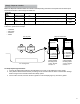
Starting Autocal When Autocal starts, it will need a reference volume as the starting point for the calibration. The default reference volume will be what the tank gauge is reading at the time that Autocal is started. This reading needs to be as accurate as possible and not higher than the initial volume read by the ATG, in order to produce a quality chart. The Diameter, Length, and Correction Points are what contribute to the default volume’s accuracy.
5. The following message will be displayed “Do you want to enter a reference volume for the autocalibration?” Reasons Why Autocal Would Stop • Power failure • Setup entered • Probe failure • TS-DIM failure • Delivery in Tank under Autocal. Autocal Completion 1. The Autocalibration procedure will stop when the Percent Coverage is reached. 2. Monitor the Daily Reconciliation and Delivery Reports for a few weeks to ensure that they are within tolerance. 6.
©2009 FFS 000-2155 RevA