Colibri Automatic Tank Gauge CL6 Series Installation Guide Franklin Fueling Systems • 3760 Marsh Rd. • Madison, WI 53718 USA Tel: +1 608 838 8786 • 800 225 9787 • Fax: +1 608 838 6433 • www.franklinfueling.
Notice FFS reserves the right to change this document and specifications at any time without notice. FFS makes no expressed or implied warranty with regard to the contents of this manual. FFS assumes no liability for errors or omissions, or for any damages, direct or consequential, that may result from the use of this document or the equipment that it describes.
Contents Important Safety Messages........................................................................................................ 1 Introduction.................................................................................................................................... 2 Product Description. .................................................................................................................... 2 Console Installation................................................................
Important Safety Messages FFS equipment is designed to be installed in association with volatile hydrocarbon liquids such as gasoline and diesel fuel. Installing or working on this equipment means working in an environment in which these highly flammable liquids may be present. Working in such a hazardous environment presents a risk of severe injury or death if these instructions and standard industry practices are not followed.
Introduction This manual contains installation and site preparation instructions for FFS’s Colibri console. Safety issues, troubleshooting information, warranty, service, and return policies, as defined in this manual, must be followed. Please read this entire manual carefully. Failure to follow the instructions in this manual may result in faulty operation, equipment damage, injury or death. Console Installation Console Location Install the console indoors in an area classified as nonhazardous.
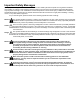
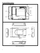
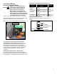
Console Dimensions 9.25" (235 mm) Probe Interface Connections Ground stud See note 2.2 1.00" (25.4 mm) Intrinsically safe wiring compartment Power / relay Compartment 2X 0.21" (5.33 mm) 2.24" (57 mm) 11.92" (303 mm) LCD Display (Optional) 7.
Standard Installation Materials Circuit Breaker 20 Amp — providing power only for the console Weatherproof Junction Boxes Minimum 16 cubic inch (406.4 cubic mm) weatherproof junction box, cover, and cover gasket for the manholes of liquid level probes. Also use ½ inch (16 mm) bushings for probe compression fittings. Use a weatherproof metal pull box for combining several circuits that will run into the console through one or more conduits.
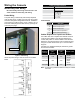
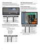
Wiring the Console Intrinsically Safe Wiring Probe Input Specifications Number of Channels: 6 Safety Rating: Class I, Division 1, Group D, [Ex ia] IIA Entity Parameters Non-intrinsically safe wiring cannot be run in the same conduit as intrinsically safe wiring. Uo = 28.35 V Io = 157.5 mA Co = 1.04 uF Lo = 1.4 mH Po = 1.1 W Probe Wiring The probe wiring is intrinsically safe and kept separate from all other wiring.
Line Power Wiring Non-Intrinsically Safe Wiring Always lock out and tag electrical Warning circuit breakers while installing or servicing this equipment and any related equipment. A potentially lethal electrical shock hazard and the possibility of an explosion or fire from a spark can result if the electrical circuit breakers are accidentally turned on during installation or servicing. Power to the console must be 110 to 240 V~, 50 / 60 Hz.
Communication Ports The Colibri console has several communication ports that can be used to communicate with devices. The communication ports can be used to connect the console to a Local Area Network, Point of Sale device, external printer or modem. USB Modem Requirements In order for the console operating system to communicate with a USB modem, the modem must be CDC-ACM compliant.
Control Drawing
©2009 FFS 000-2153 Rev.