
Installation Guide User guide


15
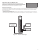
Note:
The installer must connect the earth ground conductor to the most
convenient ground terminal as long as it meets local and national codes.
The earth ground conductor must be 12 AWG (2.1 mm) or larger.
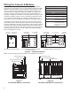
Nut
Stud: #8 threaded post
Lock Washer
Earth Ground Conductor
Enclosure
Cup Washer
Figure B-2 – Ground Stud
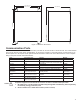
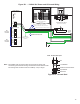
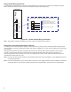
Figure B-1 – 110/240 VAC Power and IS Ground Wiring
Power Supply
Module
RUN
ERR
5V
24V
POWER
L1
N/L2
RELAY OUTPUTS
NC1
C1
NO1
NC2
C2
NO2
LOW VOLTAGE INPUTS
IN1
GND
IN2
GND
8
16
14
10
12
6
2
4
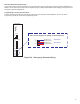
COOLER 15A
B
A
N
LIGHTS 10A
TANK 20A
SENTINEL
PUMP #1
2P-20A
3
7
15
13
9
11
5
1
16
02
15
FFO
OFF
MAIN
3 4
1 2
02
02
FFOFFO
OFF
FFO
51
FFO
01
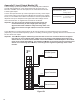
To Ground Stud
12 AWG (2.1 mm) Min.
(Figure B-2)
Redundant Intrinsic Safety Ground
Green Wire,12 AWG (2.1 mm) Min.
Electrical Power Panel
(shown with cover removed)
Neutral
Ground
Bus
- Circuit Assignment Label -
Electrical Power Panel Door
(back side view)
Black (L1-line) Wire, 14 AWG (1.6 mm) Min.
White (L2-neutral) Wire, 14 AWG (1.6 mm) Min.
Green (Gnd-ground) Wire, 12 AWG (2.1 mm) Min.
CU Earth
Ground Rod
See
Figure B-3
for details
See
Figure B-4
for details