T5 Series Fuel Management System Installation Guide Franklin Fueling Systems • 3760 Marsh Rd. • Madison, WI 53718 USA Tel: +1 608 838 8786 • 800 225 9787 • Fax: +1 608 838 6433 • www.franklinfueling.
Contents Important Safety Messages........................................................................................................ 3 Introduction.................................................................................................................................... 4 Abbreviations & Acronyms......................................................................................................... 4 Related Documentation.......................................................................
Important Safety Messages INCON equipment is designed to be installed in association with volatile hydrocarbon liquids such as gasoline and diesel fuel. Installing or working on this equipment means working in an environment in which these highly flammable liquids may be present. Working in such a hazardous environment presents a risk of severe injury or death if these instructions and standard industry practices are not followed.
Introduction This manual contains installation and site preparation instructions for INCON’s TS-5XXX series of consoles. Overall safety issues, troubleshooting information, warranty, service, and return policies, as defined in this manual, must be followed. Please read this entire manual carefully. Failure to follow the instructions in this manual may result in faulty operation, equipment damage, injury or death. This equipment should only be serviced by an INCON-certified installer.
Product Description The TS-5, TS-550 and TS-5000 are modular, automatic, continuous monitoring systems that use plug-in modules to perform a wide variety of functions. Plug-in modules now allow you to custom design your system to meet your needs by only purchasing those functions that you require, and expand your system later for greater capabilities.
TS-5 The INCON model TS-5 is an economical system that allows you to operate as efficiently as possible. The TS-5 has a variety of abilities and communication options, which enhance site management by increasing efficiency and by providing you with the data that you need to make intelligent business choices.
Standard Installation Materials Recommended standard materials should be selected and installed per all applicable local, state and federal codes governing the installation of this product and its associated systems. Please see the corresponding console/module wiring section or the associated devices section of this manual for complete installation details. Cables Required for Liquid Level Probes, VFMs & 4-20 mA Sensors Use cables and wires compliant with national and local codes.
Splice Connector Kits Must Be Used — Warranty Requirement Use the INCON-approved, moisture-resistant, no-strip splice connectors for liquid level probe and leak detection sensor wires. You may order the TSP-KW30, which contains 30 of the INCON-approved, moisture-resistant connectors. Using moisture resistant splice connectors will: • Reduce/eliminate corrosion of the wire connections from repeated exposure to water condensation, which causes eventual signal loss and system failure.
Console Installation Console Location The location that you select to install the console must be indoors in an area classified as non-hazardous (see the console specifications table at the beginning of the Wiring the Console & Modules chapter for further information). To get the maximum benefit from this system, install the console where personnel can easily make use of it; mount it at eye level for operator convenience. Mount the console level on a vertical surface between 2 feet (0.6 m) and 6 feet (1.
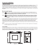
TS-550 (TS-EMS / TS-EXPC2) The TS-550 (TS-EMS / TS-EXPC2) is slightly larger than the TS-5 (TS-608) with conduit knockouts and communication ports located on the bottom of the unit. Use the diagram below to help you mount the console appropriately. 10.5" (267 mm) 8" (203 mm) 8.2" (208 mm) 11.1" (282 mm) 12.1" (307 mm) TS-550 (front view) TS-550 (side view) Figure 2 – TS-550 (TS-EMS / TS-EXPC2) TS-5000 (TS-EXPC) 16.5" (419 mm) 8" (203 mm) 14.2" (361 mm) 11.1" (282 mm) 12.
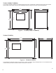
10.25" (260.4 mm) 8.25" (210 mm) 12" (305 mm) 9.00" (229 mm) Figure 4: TS-550evo Dimensions Communication Ports The T5 series consoles have several communication ports that can be used to talk to various devices. The communication ports can be used for a wide variety of applications: to connect the console to a computer network, to print reports on an external printer or to fax reports via the optional internal fax/modem.
Wiring the Console & Modules Conduit must only enter the console enclosure through the designated knockouts as shown below in Figure 6. When installing additional modules, INCON recommends installing non-IS modules from left to right (from the open slot closest to the power supply) and IS modules from right to left.
Non-Intrinsically Safe Module Wiring Danger Always lock out and tag electrical circuit breakers while installing or servicing this equipment and any related equipment. A potentially lethal electrical shock hazard and the possibility of an explosion or fire from a spark can result if the electrical circuit breakers are accidentally turned on during installation or servicing. Important: Non-intrinsically safe wiring cannot be run in the same conduit as intrinsically safe wiring.
Appendix B: Power Supply Module (PS) The PS is a non-intrinsically safe module that provides power to the T5 series console from line voltage rated 110 - 240 VAC. The PS is two inches wide, occupies two slots and is located immediately to the right of the CM. The PS consists of two AC/DC switching power supplies - one switching power supply is +5V and the other is +24V. The PS also has two relay outputs for use with remote annunciators and two low voltage inputs for emergency generator applications.
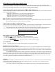
Figure B-1 – 110/240 VAC Power and IS Ground Wiring A 10 12 13 14 15 16 (back side view) N/L2 2 3 4 - Circuit Assignment Label Electrical Power Panel Door L1 1 10 8 9 11 OFF 6 20 POWER 4 COOLER 15A 7 OFF OFF TANK 20A SENTINEL 3 5 OFF 20 5V 24V 2 LIGHTS 10A OFF RUN ERR 1 15 PUMP #1 2P-20A OFF Power Supply Module MAIN N B Electrical Power Panel (shown with cover removed) Black (L1-line) Wire, 14 AWG (1.6 mm) Min. White (L2-neutral) Wire, 14 AWG (1.6 mm) Min.
Relay Output Wiring (optional) As illustrated in the diagram below, the Power Supply Module’s two relay outputs can be used to activate an external alarm (TS-RA2) and the two inputs can be used to silence that alarm remotely (TS-RK). Power Supply Module RUN ERR 5V 24V Enlarged View of Power Supply Module’s Relay Outputs POWER L1 N/L2 NC1 C1 RELAY OUTPUTS NO1 NC1 NC2 C1 NO1 C2 NC2 NO2 C2 Suggest Use - Optional: INCON TS-RA1 (or TS-RA2) & TS-RK Remote tank overfill alarm outputs.
Non-Standard Power Requirements The console’s power must be maintained on a power transfer supply for emergency backup generator applications. In addition, the T5 series’ line power must be supplied through a UPS (Uninterruptible Power Supply). See Figure B-4 for emergency generator applications. Programming & Testing Discrete Inputs Program the tank gauge and test the discrete inputs for proper operation after installation. See the T5 Series Programming Guide for reports and programming issues.
Appendix C: Relay Module (RLY) The RLY is a non-intrinsically safe module that has 8 identical Form C output channels. Each channel has a fuse and three terminals. Each channel can be configured as NO or NC with the power off by wiring to the appropriate terminals. A T5 series console can accommodate up to 24 outputs (8 outputs on up to 3 modules) as space allows. The diagrams below illustrate two examples of positive shutdown upon alarm conditions.
Appendix D: AC Input Module (ACI) The ACI is a non-intrinsically safe module that has 12 identical optically isolated AC input channels that can be used for dispenser hook isolation, vapor processor input, or as generic AC inputs. The T5 series consoles can handle a total of 36 AC inputs or up to three AC Input Modules in one system.
Appendix E: Input / Output Module (IO) The Low Voltage Input / Output Module is a non-intrinsically safe module that provides eight separate AC or DC voltage inputs that can range from 0 to 240 volts. In addition to the AC / DC inputs, the IO module also includes four 4-20mA signal outputs. The AC / DC inputs are NOT dry contact inputs (there are 2 dry contact inputs on the power supply).
Appendix F: 10 Amp Relay Module (10ARLY) The 10 Amp Relay Module is a non-intrinsically safe module that has 6 identical Form C output channels. Each channel has a fuse and three terminals. Each channel can be configured as NO or NC with the power off by wiring to the appropriate terminals. A T5 console can accommodate up to 18 outputs (6 outputs on up to 3 modules) as space allows. The diagrams below illustrate two examples of positive shutdown upon alarm conditions.
Appendix G: 4-20mA EXP Analog Input Module (420EXP) EXP Analog Input Module Specifications The 420EXP has 8 identical channels for loop powered non-IS sensors with a 4-20 mA interface. The T5 series can support up Number of Channels: 8 to 24 inputs (3 modules total including 420IB models with 8 inputs Loop Power 24 Volts Internal Resistance 350 ohms each) depending on available space in your console.
Intrinsically Safe Module Wiring Danger Always lock out and tag electrical circuit breakers while installing or servicing this equipment and any related equipment. A potentially lethal electrical shock hazard and the possibility of an explosion or fire from a spark can result if the electrical circuit breakers are accidentally turned on during installation or servicing. Important: Intrinsically safe wiring cannot be run in the same conduit as non-intrinsically safe wiring.
Appendix 1: Probe Module (PRB) The Probe Module (PRB) gathers data from probes and presents that information to the Controller Module (CM) for use in inventory reconciliation and reports. Each PRB can accomodate 12 probes and the system as a whole can accept a total of 36 probes (3 modules with 12 inputs each) if space allows. Besides working with LL2 mag probes, the PRB also works with vapor flow meters to perform VRM functions.
Appendix 2: 2-Wire Sensor Module (2WSNS) The 2-Wire Sensor Module (2WSNS) is designed to accept 12 sensor inputs per module, and the system as a whole can accept a total of 36 sensors (3 modules with 12 inputs each). The 2WSNS only supports standard sensors, and does not accept inputs from BriteSensors. Refer to the diagram below to identify some of the standard sensors that can be used with this module.
Appendix 3: 3-Wire Sensor Module (3WSNS) The 3-Wire Sensor Module (3WSNS) is designed to accept 8 sensor inputs per module, and the system as a whole can accept a total of 24 sensors (3 modules with 8 inputs each). The 3WSNS can support standard sensors and BriteSensors®. BriteSensors are powered sensors that digitally communicate the sensor–type and alarm status of the sensor to the console.
Appendix 4: 4-20mA Analog Input Module (420IB) The Analog Input Module has 8 identical channels for loop powered IS sensors with a 4-20 mA interface. The T5 series can support up to 24 inputs (3 modules with 8 inputs each) depending on available space in your console. The Analog Input Module will most likely be used with: line leak pressure transducers, tank pressure sensors and vacuum sensors.
Control Drawing 28
Specifications Warning The T5 series console must be mounted in a location where explosive or flammable vapors are not present, otherwise an explosion hazard will be created which can result in severe injury, death, serious property damage and/or environmental contamination. Console Line Voltage: 90-250 V~ Frequency & Power: 50/60 Hz, 150 W maximum Storage Temp.: -20° to 60° C (-4° to 140° F) Operating Temp.