
Installation Guide User Manual


17
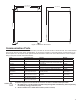
Power Supply
Module
RUN
ERR
5V
24V
POWER
L1
N/L2
RELAY OUTPUTS
NC1
C1
NO1
NC2
C2
NO2
LOW VOLTAGE INPUTS
IN1
GND
IN2
GND
PS = Discrete Inputs (Low Voltage Contacts Required)
IN1
GND
IN2
GND
Run Relay (C)
Run Relay (N.O.)
Run Relay (C)
Run Relay (N.O.)
- Generator # 1
- Generator # 2
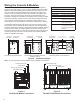
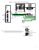
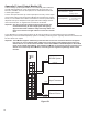
Figure B-4 – Emergency Generator Wiring
Non-Standard Power Requirements
The console’s power must be maintained on a power transfer supply for emergency backup generator applications. In
addition, the T5 series’ line power must be supplied through a UPS (Uninterruptible Power Supply). See Figure B-4 for
emergency generator applications.
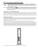
Programming & Testing Discrete Inputs
Program the tank gauge and test the discrete inputs for proper operation after installation. See the T5 Series
Programming Guide for reports and programming issues.