Fuel Management System Operator’s Guide T5 Series Franklin Fueling Systems • 3760 Marsh Rd. • Madison, WI 53718 USA Tel: +1 608 838 8786 • 800 225 9787 • Fax: +1 608 838 6433 • www.franklinfueling.
Notice Franklin Fueling Systems (FFS) reserves the right to change this document and specifications at any time without notice. FFS makes no expressed or implied warranty with regard to the contents of this manual. FFS assumes no liability for errors or omissions, or for any damages, direct or consequential, that may result from the use of this document or the equipment that it describes.
Contents Important Safety Messages............................................................................................... 1 Related Documentation............................................................................................................. 2 Introduction......................................................................................................................... 3 Definitions and Acronyms.....................................................................................
Line Leak Testing............................................................................................................... 19 Overview.................................................................................................................................... 19 Terms................................................................................................................................................ 19 Certifications – 3rd Party Approvals..............................................
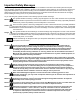
Important Safety Messages Franklin Fueling Systems (FFS) equipment is designed to be installed in association with volatile hydrocarbon liquids such as gasoline and diesel fuel. Installing or working on this equipment means working in an environment in which these highly flammable liquids may be present. Working in such a hazardous environment presents a risk of severe injury or death if these instructions and standard industry practices are not followed.
Certified Programmer/Service Person: Only an INCON certified programmer or service person is allowed to access both the user interface keypad and areas internal to the Fuel Management System console. Station Owner/Operator: The station owner or operator of the Fuel Management System console is only allowed to access the user interface keypad. Access to areas internal to the console is strictly prohibited.
Introduction The purpose of this manual is to guide installers, operators and technicians through the operation of a T5 series console. The T5 series consoles incorporate the monitoring and alarm capabilities of preceding automatic tank gauges with advanced technologies to supply tank and level data more accurately and efficiently.
Applications Applications are programs designed to function as a platform for specific Inputs/Outputs. There are two different applications available to the T5 series consoles: System – This application is standard on all systems and monitors the console’s operational status and manages software options and upgrades. All preferences and configuration settings are controlled by this application (e.g., display options, clock and calendar). The system application is standard on every console.
Optional Modules 2-Wire Sensor Module Provides 12 inputs for 2-wire Standard sensors. 3-Wire Sensor Module Provides 8 inputs and supports both 3-wire and 2-wire sensors. 4-20 mA Input Module Provides 8 inputs that can be used for TS-LS500 line leak detection transducers. 4-20 mA EXP Explosion-proof module. Otherwise the same as the 4-20 mA Input Module. AC Input Module Provides 12 inputs for dispenser hook signals, which are also required for LLD. This module replaces external DHI boxes.
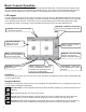
Basic Console Operation Once the Fuel Management System has been installed, programmed and tested, you will interact with the system via the LCD touch screen and printer or the Web Browser Interface via a PC. This section of the manual will describe the operation of the console using a touch screen. Information on the Web Browser Interface can be found in later chapters. LCD Layout The LCD interface is designed so that a user may navigate the system with ease.
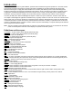
Data Entry If you are prompted to enter information, a keypad and edit buttons will be displayed. Character Selection: Selects between upper case letters, lower case letters and numerals. The characters on the keypad will change as you scroll through the options. Backspace: Deletes the previous character. Clear: Deletes all of the data on the entry line. Enter: Allows the data to be accepted. When this button is pushed, the configuration will be set for the item you are changing.
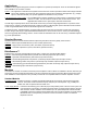
Main (Home) Menu Options The Main Menu button will take you to the Home/Menu screen where you can select from several different options. The first six are displayed; use the Down button to see the rest of the choices. Setup Performing console setup and programming (Administrator Use Only). Preferences Configure the way information will be displayed. Configuration Set certain system parameters. Reports Print various reports when an optional printer is attached.
Reports Menu Use the Reports Menu to generate a variety of reports and access report menus for all available applications. Alarm History Print a history of alarms. FMS Access the FMS reports menu. System Print system status reports. Diagnostics Menu Use the Diagnostics Menu to test the operation of certain components of the system. Test Annunciator Tests the operation of the internal alarm. Print Test Page Sends a test page to any optional printer.
Fuel Management System Application The Fuel Management Systems application provides inventory management, optional tank and line leak detection features and sensor monitoring. Select FMS in the Application window of the Home screen. FMS Inventory Summary Menu The FMS Inventory Summary displays a graphical representation of the product and water levels in the tank and indicates any alarm conditions. The Product name and current Volume are also displayed for each tank.
Printing Reports Internal Printer An internal printer is optional on TS-550/5000 FMS consoles, but not available on the TS-5 (TS-608) console. It is an impact style printer that uses standard printer paper and has a replaceable ribbon cartridge. For paper loading and ribbon replacement instructions, refer to the Routine Maintenance chapter in this manual. External Printers External printing is accomplished via USB. No software drivers need to be installed to print via USB.
Tank Testing There are two types of Tank Testing available in the Fuel Management Systems: Static and SCALD. Static tests are run during quiet times when the tank is thermally stable and the site is closed so that no dispensing or deliveries will occur. There are two types of Static tests: Monthly (0.2 gph) and Annual (0.1 gph). Static tests can be scheduled to run on a Daily, Weekly or Monthly basis in the Setup menu (Administrator use only). They can also be started on demand from the FMS > Control menu.
Tank Testing Requirements Static Tank Testing is available only if the option for Tank Testing is enabled. This option can be ordered when purchasing the console or after initial purchase by using the part number TS-TT. The software option includes both Static and SCALD (continuous) leak testing. For TS-5 and TS-608 consoles, Static Tank Testing is included as standard programming. SCALD is an option. To perform tank testing, the Tank Testing software must be enabled.
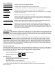
How to Manually Start Static Tests This procedure requires User level privileges. 1. Starting at the Home/Status screen, press the FMS application button. 2. Press the Application Menu button. 3. Press the Control button. Step 1 Step 2 Step 3 4. Press the Tanks button. 5. Select the tank that will be tested. If the tank does not appear on the screen, use the Scroll Down button to view more options. 6. Press the Test Type and choose either Monthly or Yearly. Step 4 Step 5 Step 6 7.
Statistical Continuous Automatic Leak Detection (SCALD) SCALD (Statistical Continuous Automatic Leak Detection) runs 24hrs a day performing 0.2 GPH tests on tanks at sites that do not have enough quiet time to complete static tests (some static tests may take up to eight hours to complete). SCALD Testing is available only if the option for Tank Testing is enabled. This option can be ordered when initially purchasing the console or afterwards.
SCALD Results Pass – A passing result ensures the integrity of the tank is good. Fail – Test failure will be indicated by a Warning light and/or annunciator. Additionally, a report may print (if the console is programmed to do so, see the T5 Programming Guide - p/n 000-2142) Abort – The result is due to variations in float level and/or product temperature that are outside the leak test threshold.
Example Tank Leak Test Reports from Internal Printer Site ID 1 Site ID 2 Site ID 3 Site ID 4 Site ID 5 Date Time Site ID 1 Site ID 2 Site ID 3 Site ID 4 Site ID 5 Date Tank Test Report SCALD Report Specified Time Frame Specified Time Frame Volume: (gal) programmed Length: (in) programmed Temperature: (F) programmed TANKS Volume: (gal) programmed Length: (in) programmed Temperature: (F) programmed TANKS Tank # Product # Maximum Capacity #.## Begin Time Date Time Begin Gross #.# Begin Net #.
Example External Tank Leak Test Report from Web Browser Interface Site ID 1 Site ID 2 Site ID 3 Site ID 4 Site ID 5 Date Time Last Available Tank Test Report STATIC TEST TANKS Name Max Capacity Tank # #.## Gross Volume Time Started Ended Last Delivery Threshold Net Volume #.## #.## #.## Date Time Date Time Date Time Programmed Net Volume #.# #.# Test Type Capacity Temperature ##.## ##.## ##.## Site ID 1 Site ID 2 Site ID 3 Site ID 4 Site ID 5 #.# #.# (Monthly) #.
Line Leak Testing Overview Line Leak Detection is available only if the option for Line Testing is enabled. This option can be ordered when purchasing the console or after the initial purchase by using the part number TS-ELLD. Relay, AC Input and 4-20mA Modules will also need to be ordered and installed, if not initially purchased with the console. The TS-5 and TS-608 FMS consoles do not have line leak detection capabilities.
Test Cycles & Types Once installed, calibrated and enabled, the LS500 will start a cycle of tests after the hook signal becomes inactive (i.e. a nozzle is hung up). The transducers then monitor line pressure to ensure that pressure is sufficient to proceed with the cycle. A Gross (3.0 GPH) Leak Test will begin immediately following the pressure test, if these options are enabled in setup.
4. Press the Lines button. 5. Select the line that will be tested. If the line does not appear on the screen, use the Scroll Down button to view more options. 6. Press the Test Type, either Force Gross, Force Annual or Force Monthly. 7. Press the Checkmark button to start the test. Step 4 Step 5 Steps 6 & 7 Line Test Results Pass – A passing result ensures that the line is free of leaks; any variation in product stability is within permissible thresholds.
Line Leak Test Reports Reports that contain leak testing data and results may be printed from the console or generated/printed using TSA. Printing Tank Leak Test Reports LCD 1. Starting at the Home/Status screen, press the Reports button. 2. Press the FMS button. 3. Press the Line Test row. 4. Select the Time Option desired. 5. Press the checkmark to start report printing.
Example Line Leak External Test Reports from Web Browser Interface Site ID 1 Site ID 2 Site ID 3 Site ID 4 Site ID 5 Name Result Line # Daily Total = # Gross Leak Test ‘Result’ Name Result Line # Daily Total = # Monthly Leak Test ‘Result’ Name Result Line # Daily Total = # Annual Leak Test ‘Result’ Date Time Last Available Line Leak Report GROSS TEST Test Date Date MONTHLY TEST Test Date Date ANNUAL TEST Time Time Test Date D
Web Browser Interface One of the most powerful advantages of a T5 series console is its standard Ethernet port and ability to communicate with a web browser via web pages using standard XML (eXtensible Markup Language) protocols. The Web Browser Interface allows the Fuel Management System to directly connect to a PC through a local area network or high speed internet connection.
Available Pages The following web pages can be browsed to in order to access data and perform various control functions. Some of the pages are dependent on the version of console and the options installed. Several pages and functions are access level controlled. If the Auto Refresh action is listed on the Action Bar of a page, then the data on the page does not refresh automatically. Click Refresh on your browser to update the page or click on Auto Refresh to do this continuously.
Routine Maintenance As an end user/owner, there is a limited amount of maintenance that you may need to perform on the console. To keep the unit in good, serviceable condition, follow the procedures outlined below. Warning Do not attempt to open the console unless you are a certified INCON technician. Electrical hazards exist and injury or death may occur if the console interior is accessed by unauthorized personnel.
Appendix A – Compatible Printers T5 Series Fuel Management Systems – Hewlett Packard Compatible Printers T5 series consoles come equipped with a standard Type-A USB socket located on the bottom (TS-550/5000) or side (TS-5) of the console near the other communications ports. The T5 series consoles utilize Printer Control Language (PCL) version 3 or higher protocol developed by Hewlett Packard (HP) to print to external printers.
Appendix B – Alarm Table Note: Refer to Safety Instructions outlined in this manual prior to performing any maintenance on or inside the console. Note: If at any time while troubleshooting a Warning or Alarm this guide does not correct the issue, contact FFS Technical Services. Warning Always remove power from the console prior to installing or removing a module or performing any maintenance while the console door is open.
System Displayed Warning IS Barrier Violation Low Battery Description The system has received an indication that there is a Non-Intrinsically Safe module installed in the IS area or that the IS barrier has been removed. Backup Battery should be replaced. Modem Error The number of expected Modem Modules does not equal the number of Modem Modules installed. Power Supply Module is Offline This warning is only possible if there is a TS-EXPC expansion console connected.
FMS Tank/Manifold Alarms Displayed Alarm Correction Table Error Manifold Gross Leak Detected Manifold Leak Detected Manifold SCALD Leak Detected Manifold Theft Detected No Data Available Tank Gross Leak Detected Tank Leak Detected Tank SCALD Leak Detected Tank Theft Detected Description Recommended Actions Reference Source Correction points for the special Verify that the correction table points for the tank Special Tanks Setup in tank listed with the alarm were not listed with the alarm are entered seque
FMS Probe Alarms Displayed Alarm Description Float Height A float on the probe listed with the alarm is Error being monitored at a varying height outside of thresholds. Causes can include broken float and programming, or mistakenly associating a gasoline and diesel float. Float Missing A float on the probe listed with the alarm has not been detected or the probe was programmed with the incorrect number of floats.
FMS Line/Manifold Alarms Displayed Alarm Dispenser Test Failed Description Line pressure must be above 12 psi when the pump is on; and above 7.5 psi while dispensing product. A hook signal has been active for more than four hours. Recommended Actions Details of this test are summarized in LS500 Installation/User Guide (p/n 000-2145); see this guide for troubleshooting.
FMS Special Product Alarms Displayed Alarm Alpha Volume Correction Error API Volume Correction Error Level Error Net Error Product Volume Error Ullage Error Water Volume Error Description These Alarms refer to temperature correction coefficients used by the console to calculate Net Volume. When these values are entered too high or too low, an alarm condition will occur.
FMS Sensor Alarms Displayed Alarm SN2 Fuse Blown SN2 Sensor On SN3 Dry Well SN3 Fuse Blown SN3 Sensor On SN3 Sync Error SN3 No Signal SN3 ID Error SN3 Data Error SN3 Pwr Short SN3 High Brine SN3 Low Brine SN3 Product SN3 Sump Full SN3 Vapor SN3 Water Description The fuse on the channel of the 2-Wire Sensor Module listed with the alarm is blown. The 2-Wire Sensor listed with the alarm is in alarm position. The Monitoring Well Sensor listed with the alarm is not sensing water in the monitoring well.
Franklin Fueling Systems C Page 1 of 2 Appendix C – Third Party Certifications Issue Date: November 22, 1995 Revision Date: February 28, 2006 Franklin Fueling Systems TS-750, TS-1000, TS-1001, TS-2001, TS-5, TS-608, TS-550, TS-5000 (INCON Magnetostrictive Probe) AUTOMATIC TANK GAUGING METHOD Certification Leak rate of 0.2 gph with PD = 95.7% and PFA = 4.3%. Leak rate of 0.1 gph with PD = 99.9% and PFA = 0.1%. Leak Threshold 0.1 gph for leak rate of 0.2 gph. 0.05 gph for leak rate of 0.1 gph.
Comments Not evaluated using manifolded tank systems. Therefore, this certification is only applicable when there is a probe used in each tank and the siphon is broken during testing. Tests only portion of tank containing product. As product level is lowered, leak rate in a leaking tank decreases (due to lower head pressure). Consistent testing at low levels could allow a leak to remain undetected.
Issue Date: July 27, 2006 Franklin Fueling Systems TS 750, 1000, 1001, 2000, 2001 with SCALD 2.0, TS-5, TS-608, TS-550, TS-5000 (INCON TSP-LL2 Magnetostrictive Probe) CONTINUOUS IN-TANK LEAK DETECTION METHOD (CONTINUOUS AUTOMATIC TANK GAUGING) Certification Leak rate of 0.2 gph with PD > 99% and PFA < 1%. Leak Threshold 0.10 gph for single and manifolded tank systems.
The database for evaluation of the system includes sites with vapor recovery and blending dispensers. Franklin Fueling Systems 3760 Marsh Road Madison, WI 53718 Tel: (800) 225-9787 E-mail: info@franklinfueling.com URL: www.franklinfueling.com Evaluator: Ken Wilcox Associates Tel: (816) 443-2494 Dates of Evaluations: 07/11/2003, 03/18/06 From the National Work Group on Leak Detection (NWGLDE) web site. 20 Feb. 2007.
Issue Date: May 19, 2006 Franklin Fueling Systems TS-LS500 Series (for Rigid and/or Flexible Piping) AUTOMATIC ELECTRONIC LINE LEAK DETECTOR Certification Leak rate of 3.0 gph at 10 psi* with PD = 100% and PFA = 0%. Leak rate of 0.2 gph at operating pressure with PD = 100% and PFA = 0%. Leak rate of 0.1 gph at 1.5 times operating pressure* with PD = 100% and PFA = 0%.
Franklin Fueling Systems 3760 Marsh Road Madison, WI 53718 Tel: (800) 225-9787 E-mail: info@franklinfueling.com URL: www.franklinfueling.com Evaluator: Ken Wilcox Associates Tel: (816) 443-2494 Dates of Evaluation: 06/23/95, 09/10/98, 02/28/06 From the National Work Group on Leak Detection (NWGLDE) web site. 20 Feb. 2007.
Issue Date: November 17, 2005 Franklin Fueling Systems Secondary Containment Monitoring (SCM) Incon TS-SCM and EBW AS-SCM CONTINUOUS INTERSTITIAL TANK SYSTEM MONITORING METHOD (PRESSURE/VACUUM) Certification: Certified as equivalent to European leak detection standard EN 13160-2, Part 2, as a Class I leak detection system.
Comments: Interstitial space is tested continuously. Vacuum source is the submerged turbine pump siphon port. Presence of a water table above the leak point will allow water to enter the interstice rather than air or vapor. The water would be detected in the same manner as fuel. This system may not be compatible with all secondarily contained tanks and/or piping.
©2009 FFS 000-2151 Rev.