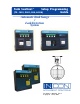
Tank Sentinel ® Setup Programming Guide (TS - 1001, 2001, 504, & 508) Automatic Tank Gauge / Leak Detection System Part Number: 000-1053, Rev.
NOTICE INCON has strived to produce the finest possible manual for you, and to ensure that the information contained in it is complete and accurate. However, INCON makes no expressed or implied warranty with regard to its contents. INCON assumes no liability for errors or omissions, or for any damages, direct or consequential, that result from the use of this document or the equipment which it describes. This document contains proprietary information and is protected by copyright. All rights are reserved.
Table of Contents P Preface ................................................................................................... P - i Graphic Symbol Conventions ..................................................................................... P - i Page Numbering Convention ................................................................................. P - i Page Layout Convention .......................................................................................
5 Products Setup Programming ............................................................. 5 - 1 Products Menu ............................................................................................................ 5 - 1 SPECIAL PRODUCTS Menu ..................................................................................... 5 - 2 6 Manifolds Setup Programming ............................................................ 6 - 1 Manifolds Menu ...........................................................
Monthly Sales Report: ............................................................................. 9 - 11 Shift History Report: ................................................................................ 9 - 11 Daily History Report: ............................................................................... 9 - 11 10 Leak Test Setup Programming .......................................................... 10 - 1 Leak Test Menu (Static Tank) ...........................................................
TS-ROM Channel 6 TS-ROM Channel 7 TS-ROM Channel 8 Output Group (alarm assignment) ..................... 16 - 3 Output Group (alarm assignment) ..................... 16 - 3 Output Group (alarm assignment) ..................... 16 - 4 17 Sensors (Leak Detection) Setup Programming ................................. 17 - 1 Sensors Menu ............................................................................................................ 17 - 1 Naming Sensors .............................................
24 Language Selection Menu ................................................................... 24 - 1 Language Selection Menu .......................................................................................... 24 - 1 Language Selection Notes ............................................................................. 24 - 1 25 Data Log Menu .................................................................................... 25 - 1 Data Log Menu ......................................................
Table of FIGURES and TABLES Page Layout Convention ................................................................................. P - i Figure 2 - 1 Typical Tank Limits ....................................................................... 2 - 3 TABLE TABLE TABLE TABLE TABLE TABLE TABLE 4.1 SPECIAL PROBE RTD POSITIONS .......................................... 4 - 5 9.1 TYPICAL REPORT SCHEDULE ................................................. 9 - 1 9.2 24 HOUR TIME INPUT FORMAT .......................
P PREFACE Contents: Graphic Symbol, Page # & Layout Conventions Before you Begin – Site Information Required – Other Sources of Info. Scope of This Manual Programming I/O Module Menu Conventions, Key Operation Action, Alpha-Numeric Input Interfacing TS-LLD to Tank Programming Alarm, Limits, Gauge or Inputs to Output Groups Leaving (Exit) Setup Programming Output Devices Programming Graphic Symbol Conventions NOTE ☞ Important information, tips, and hints are highlighted by the NOTE graphic.
BeforeYou Begin – Read This CAUTION Leaking underground storage tanks ( USTs ) and fuel lines cause serious environmental and health hazards. The Tank Sentinel® system is designed to detect leaks in tanks by tank tightness / leak testing with liquid level probes, and/or with leak detection sensors. You must follow the instructions in this manual carefully to ensure that the system is programmed properly and is effective in detecting leaks.
Scope of This Manual This manual shows the setup-programming of Tank Sentinel system. Each Chapter is dedicated to a specific parent menu (see Parent Menus below). Menu Conventions The menu structure in this manual is shown in an indented format: PARENT MENUs are above and to the left of sub-menus and SUB-MENUs are below and to the right of parent menus. Default VALUES, SETPOINTS, & LIMITS are shown first and in ITALIC text.
Key Action (CONTINUED FROM PREVIOUS PAGE... ) • ACK SHIFT key is used to change the preconditioned input character type... the display shows either an A...M or the word NUMERIC when an alphanumeric or numeric input is expected. Press the ACK SHIFT key N times to change the current input character type to another type (look at the upper right corner of display while doing this).
Programming Alarms, Limits, or Inputs to Output Groups The TS-1001/504 / 2001/508 Tank Sentinels includes a powerful setup feature called – Output Groups (OGs). Alarms, limits, and inputs (Aux. or I/O Module inputs) can be assigned / programmed to output groups (OUT GROUP or OG). An output device will turn on or off when an alarm is active in any of its assigned output group(s). Up to 32 output group(s) can be assigned or programmed to any output device... also see Programming Output Devices.
Programming Output Devices: After assigning alarms and limits to output group(s), program the appropriate output devices to respond to any or all output groups (OGs) Example Applications: Turn on external Tank Overfill Alarm & solid console annunciator (when a high or high high product level – alarm limit is reached) Program the (above) alarm limits for each tank. Assign the associated H LIM OG or HH LIM OG output groups to one alarm group for each tank (ie GROUP O).
Standard and Optional Output Devices Standard Output Devices: Optional (TS-CIM / TS-IEM) Output Devices : Modulated Annunciator I/O Module Output 1* Solid Annunciator I/O Module Output 2* Relay 1 I/O Module Output 3* Relay 2 I/O Module Output 4* Optional Output Devices: I/O Module Output 5* TS-ROM Relay 1 I/O Module Output 6* TS-ROM Relay 2 I/O Module Output 7* TS-ROM Relay 3 I/O Module Output 8* TS-ROM Relay 4 I/O Module Output # 9* I/O Module Output # 10* TS-ROM Relay 5 I/O Module Ou
Leaving (Exit) Setup Programming There are two ways to leave the setup mode. These are: 1.) Use (press) the CANCEL key until the exit choice appears, then press the M1 key to exit the setup mode. SETUP MENU EXIT SYSTEM M1 TANKS M2 M3 (MORE) PROBES M4 – or – 2.) Wait until the Tank Sentinel console autoexits. NOTE ☞ The unit will automatically leave / exit the setup mode ( autoexit ) after three or four minutes of inactivity (if no key is pressed).
1 System SETUP PROGRAMMING Contents: System Menu Worksheet 1-1 — System Output Groups System Menu H See the Table of Contents to find topics in this manual. See the Preface for general information about this manual. See the Installation, Operator’s, TroubleShooting Guides and Application Notes for other reference sources. NOTE ☞ The NO.
SYSTEM Menu (CONTINUED... FROM PREVIOUS PAGE) SYSTEM ID (enter new 5 line report header, see below) Default Report Header Ø LINE 1 LOCATION LINE 1 INCON enter up to 24 characters max. Press ENTER to accept this data. LINE 2 LOCATION LINE 2 INTELLIGENT CONTROLS enter up to 24 characters max. Press ENTER to accept this data. LINE 3 LOCATION LINE 3 P. O. BOX 638 enter up to 24 characters max. Press ENTER to accept this data. LINE 4 LOCATION LINE 4 SACO ME 04072 enter up to 24 characters max.
SYSTEM Menu (CONTINUED... FROM PREVIOUS PAGE) NO. SENSORS NUMBER OF SENSORS 12 (for TS-1001, 504) 24 (for TS-2001, 508) (enter the number of Leak Detection Sensors) NO. METERS NUMBER OF METERS 0 (devices used with TS-DIM) BUSY ENA BUSY ENABLED NO YES U THRESH USER THRESHOLD +0 LIMITS LIMITS LEAK LIM LEAK LIMIT +2.0 (0 thru N) enter the total number of Sensors. (also enter all unused channels between the lowest to highest channel (also see SENSORS menu) Press ENTER to accept this data.
SYSTEM Menu (CONTINUED... FROM PREVIOUS PAGE) SENTINEL SENTINEL MODE MODE SENTINEL MODE OFF SCHEDULED (after hours theft monitoring / tank leak detection) Use UP/DOWN ▲ ▼ keys to choose mode. Press ENTER to accept this data. Select SCHEDULED to enable Sentinel Mode — START TIM SENTINEL START TIME 00.00.00 up to 23.59.59 END TIME SENTINEL END TIME 00.00.00 up to 23.59.
SYSTEM Menu (CONTINUED... FROM PREVIOUS PAGE) REP LINES REPORT LINE TESTS ENABLED DISABLED (Appears only if an L is present in the TS Part Number (press CHECK and M4 to view OPTIONS) Use UP/DOWN ▲ ▼ keys to choose. Press ENTER to accept this data. (enabled = yes, report LINE leak tests) (disabled = no, don’t report LINE leak tests) HIST SIZE HISTORY REPORT LENGTH 50 (Max.
Worksheet #1-1 – Output Groups – System Limits Fill-in the work sheet below and compare assignments to uncover conflicts before programming output devices.
— Your Notes — — ❖ — System Setup Page 1 - 7 1
2 Tanks SETUP PROGRAMMING Contents: Tank Data Menu Tank Alarm Menu Special Tank Menu Worksheet 2-1, 2-2 Tank Output Groups Tanks Menu H See the Table of Contents to find topics in this manual. See the Preface for general information about this manual. See the Installation, Operator’s, TroubleShooting Guides and Application Notes for other reference sources. NOTE ☞ U MENU 7 × Press this key and follow the highlighted sequence below SELECT MENU OPTION SETUP UPGRADE LANGUAGE DATALOG Only the NO.
Tanks – TANK DATA N Menu (CONTINUED...FROM PREVIOUS PAGE) N refers to / represents a tank number (Use SHIFT to change from A-M to N-Z to NUMERIC.) NAME TANK NAME N TANK N enter up to 7 characters max. Press ENTER to accept this data.
Tanks – TANK DATA N Menu (CONTINUED... FROM PREVIOUS PAGE) P OFFSET PRODUCT OFFSET N +0.00000 (to compensate product readings from tank tilts) W OFFSET WATER OFFSET N +0.00000 (to compensate product readings from tank tilts) DEL THRES DELIVERY THRESHOLD N +200.000 (the minimum volume before a delivery is reported) +20 to -20 Use keypad to input level units. Press ENTER to accept this data.
Tanks – TANK DATA N Menu (CONTINUED...FROM PREVIOUS PAGE) TANK ALARM N COPY COPY FROM TANK ALARMS X TO N TANK 1 : TANK 8 COPY TANK ALARMS X TO N PRESS ENTER IF YOU ARE SURE? HIGH LIM HIGH PRODUCT LEVEL LIMIT N +96.0000 To select Tank N ... (COPY is optional) Press the M1 key. Select a tank to copy data from (use M key). Use UP/DOWN ▲▼ keys to display tanks 5-8. (The alarm copy function copies all alarm limits from Tank X to the current Tank # N) Press ENTER to accept this data. 0.0 to 9999.
Tanks –TANK ALARM N Menu (CONTINUED...FROM PREVIOUS PAGE) LL LIM OG N L L PRODUCT OUTPUT GROUP N NONE GROUP A-FF ALL GROUPS WATER LIM N HIGH WATER LEVEL LIMIT N +4.0000 W LIM OG N HIGH WATER OUTPUT GROUP N NONE GROUP A-FF ALL GROUPS NOTE ☞ (assign Alarm Limits to Output Group) (32 OGs available... see Worksheet #2 or #3) Not assigned to an output Group (OG) One OG selected ( A = 1ST OG, FF = 32ND OG ) All OGs selected Use UP/DOWN ▲ ▼ keys to choose an OG. Press ENTER to accept this data. 0.0 to 9999.
Tanks – SPECIALTANK N Menu (CONTINUED) SPECIAL TANK N COPY COPY FROM SPECIAL TANK X TO N SPECIAL 1 COPY SPECIAL TANK N TO N PRESS ENTER IF YOU ARE SURE? N refers to / represents a tank number Press the M1 key. Select a tank to copy data from (use M key). Press ENTER to accept this data. Use UP/DOWN ▲▼ keys to display tanks 5-8. Press the M2 key. DIAMETER TANK DIAMETER N +96.00 0.0 to 999,999 Use the M4 key to use BACKSPACE. Use the Keypad to input the special tank diameter.
Tanks – SPECIALTANK N Menu (CONTINUED) DELETE SELECT POSITION WITH UP/DN LEVEL +X VOLUME +Y POS # Press ENTER to accept this data. ARE YOU SURE? EDIT SELECT POSITION WITH UP/DN LEVEL +X VOLUME +Y DISPLAY CORRECTION TABLE N POS LEVEL +X VOLUME +Y Select the POS # to delete (UP/DOWN ▲▼). Press ENTER to accept this data. POS # Select POS # to edit (UP/DOWN ▲▼). Press ENTER to accept this data. (correct the mistake and press ENTER again) N Use UP/DOWN ▲▼ keys to scroll thru list.
Worksheet #2-1 – Output Groups – Tanks 1 thru 4 Fill-in the work sheet below and compare assignments with other work-sheets to uncover conflicts before programming output devices (for ALL ATG types).
Worksheet #2-2 – Output Groups – Tanks 5 thru 8 Fill-in the work sheet below and compare assignments with other work-sheets to uncover conflicts before programming output devices (for TS-2001 / 508 only).
— Your Notes — — ❖ — 2 Page 2 - 10 Tank Sentinel Setup Programming Guide
3 Lines SETUP PROGRAMMING Contents: Lines Menu Line Data Menu Lines Menu H See the Table of Contents to find topics in this manual. See the Preface for general information about this manual. And see the Installation, Operator’s, TroubleShooting Guides, and Application Notes for other reference material. NOTE ☞ U MENU 7 × Press this key and follow the highlighted sequence below SELECT MENU OPTION SETUP UPGRADE LANGUAGE M1 M2 SETUP MENU EXIT SYSTEM M3 TANKS Only the NO.
Line Data Menu LINE DATA LINE 1 LINE 2 : LINE 8 LINE DATA N NAME LINE NAME N LINE N Select a line. Use UP/DOWN ▲ ▼ keys to display Lines 5 – 8. LINE N is shown typical for any line # Use keypad to input / edit name (9 characters max.). Press ENTER to accept this data.
4 Probes SETUP PROGRAMMING Contents: See the Table of Contents to find topics in Probes Menu this manual. See the Preface for general Probe Data Menu information about this manual. And see the Special Probes Menu Installation, Operator’s, TroubleShooting TABLE 4.1 Special Probe RTD Guides, and Application Notes for other Positions reference material.
Probes – PROBE DATA Menu (CONTINUED...FROM PREVIOUS PAGE) PROBE DATA N TYPE PROBE TYPE FOR PROBE N STD 101 STD 107 STD 113 : STD 149 SPEC PROBE 1 SPEC PROBE 2 : SPEC PROBE 8 PRESSURE STD 29 : STD 89 PROBE # N shown typical for any probe # 1 – # 8 Press M2 key. Press UP/DOWN ▲ ▼ keys to choose. Press ENTER to accept this data. STD # probe is a STANDARD probe. (menus differ depending on choices) Select SPEC PROBE N (special probe) if it is not a Standard TSP-LL2 model / type of probe listed in this menu...
Probes – PRESSURE PROBE DATA Menu NOTE ☞ This grayed out section is a duplicate of the STANDARD menu - use it to assist in following the PRESSURE PROBE DATA MENU. PROBE DATA N COPY PROBE DATA N TYPE PROBE TYPE FOR PROBE N PRESSURE MODEL PROBE MODEL FOR PROBE N SCALE (TS-ISCB) SCALE N +9.03000 OFFSET(TSP-ISCB) PROBE OFFSET N +0 PROBE # N shown typical for any probe # 1 – # 8. Press M1 key. PROBE # N shown typical for any probe # 1 – # 8. Press M2 key. Press UP/DOWN ▲ ▼ keys to choose probe type.
Probes – SPECIAL Menu PROBES D ATA M1 The SPECIAL menu appears when at least one SPEC PROBE N was selected from the PROBES – DATA – TYPE menu (above). SPECIAL M2 M3 SPECIAL SPECIAL PROBES SPECIAL 1 SPECIAL 2 : SPECIAL 8 SPECIAL PROBE N M4 This menu shows all possible choices BUT only the selected SPECIAL PROBES N are displayed. Press (M) key to select a SPECIAL # probe. N = Special Probe # 1 thru # 8 and may or may not agree with the actual Tank number or Probe input channel number.
Probes – SPECIAL Menu (CONTINUED... FROM PREVIOUS PAGE) Steps: 1.) Accurately fill-in TABLE 4.1 RTD POSITION TABLE N (ref. Install. Guide / Probe head / cable) 6.10 2.) Add RTD position accurately 3.) Repeat step 2 until all positions are added RTD POSITION TABLE N 16.63 4.) Display / check RTD table N positions 5.) Edit / Delete positions as required RTD POSITION TABLE N 24.69 6.) Repeat step 5 to confirm accuracy POS 1 POS 2 POS 3 RTD POSITION TABLE N 32.64 POS 4 RTD POSITION TABLE N 41.
— Your Notes — — ❖ — 4 Page 4 - 6 Tank Sentinel Setup Programming Guide
5 Products SETUP PROGRAMMING Contents: Products Menu Product Data Menu Special Product Menu See the Table of Contents to find topics in this manual. See the Preface for general information about this manual. And see the Installation, Operator’s, TroubleShooting Guides, and Application Notes for other reference material.
Product Data Menu (CONTINUED... FROM PREVIOUS PAGE) COPY FROM PRODUCT DATA X TO N PRODUCT 1 PRODUCT 2 : PRODUCT 8 COPY PRODUCT DATA X TO N PRESS ENTER IF YOU ARE SURE? Press (M) key to select a PRODUCT # to copy. Press UP/DOWN ▲ ▼ to display product in tanks 5 – 8. Press ENTER to accpept this data. (press CANCEL to prevent copying product data) (rename product if necessary) Press M2 key. NAME PRODUCT NAME N PROD N 9 characters (ie.
Special Products Menu (CONTINUED... FROM PREVIOUS PAGE) COPY SPECIAL PRODUCT X TO N PRESS ENTER IF YOU ARE SURE? Press ENTER to accept this data. (press CANCEL to prevent copying data) TMP CTYPE (Temperature Compensation Type) Press M2 key. TEMPERATURE COMPENSATION TYPE N Press UP/DOWN ▲ ▼ to choose a type. API 6B/54B API 6C/54C (changes API GRAV to DENSITY) API 6A/54A Press ENTER to accept this data. API GRAV API GRAVITY N +63.5000 Press M3 key. DENSITY DENSITY N +63.5000 Press M3 key. 0.0 to 100.
— Your Notes — — ❖ — 5 Page 5- 4 Tank Sentinel Setup Programming Guide
6 Manifolds SETUP PROGRAMMING Contents: Manifolds Menu Manifold Data Menu Manifold Alarms Menu Worksheet 6-1 – Manifolds 1 thru 4 NOTE Manifolds Menu H ☞ U MENU 7 × Press this key and follow the highlighted sequence below SELECT MENU OPTION SETUP UPGRADE LANGUAGE M1 M2 SETUP MENU EXIT SYSTEM M3 TANKS DATALOG M4 (MORE) PROBES ▼ Press the DOWN key ▼ SETUP MENU PRODUCTS MANIFOLDS M1 M2 REPORTS (MORE) LK TSTS M3 M4 M3 M4 MANIFOLDS DATA ALARMS M1 M2 See the Table of Contents to find
Manifolds Data Menu (CONTINUED... FROM PREVIOUS PAGE) NAME MANIFOLD NAME N MAN N Press M2 key. 9 characters Use keypad to input a name for the Manifold. Press ENTER to accept this data. PRODUCT Press M3 key. PRODUCT FOR MANIFOLD N PRODUCT 1 Press UP/DOWN ▲ ▼ to select a product #. : PRODUCT 8 Press ENTER to accept this data. ( If tanks are set to manifold, then the product section of the tank menu disappears ) DEL THRES Press M4 key. DELIVERY THRESHOLD N +200.000 1 to 99999.
Manifolds ALARMS Menu (CONTINUED... FROM PREVIOUSPAGE) LOW LOW LOW LOW PRODUCT VOLUME LIMIT N +0.0000 Press M4 key. + 0 to 50000 Use keypad to input alarm limits. Press ENTER to accept this data. LL LIM OG Press M1 key. LOW LOW PRODUCT LIMIT OUTPUT GRP Press UP/DOWN ▲ ▼ to assign alarm to (OG) N NONE Not assigned to an OG GROUP A-FF One OG selected (A=1st OG, FF=32nd OG) ALL GROUPS All OGs selected (see WORKSHEET #6-1) Press ENTER to accept this data.
Worksheet # 6-1 – Output Groups – Manifolds 1 thru 4 Fill-in the work sheet below and compare the assignments with other work-sheets to uncover conflicts before programming output devices.
— Your Notes — — ❖ — Manifolds Setup Page 6 - 5 6
7 Reconciliation SETUP PROGRAMMING Contents: See the Table of Contents to find topics in this manual. See the Preface for general information about this manual. And see the Installation, Operator’s, TroubleShooting Guides, and Application Notes for other reference material.
Reconciliation menu (Continued... FROM PREVIOUS PAGE) Use UP/DOWN ▲ ▼ keys to choose SHIFT or DAILY. (nothing scheduled) (set times for a three-shift working day) (set the one time during the day to start) Press ENTER to accept this data. RECONCILIATION SCHEDULE NONE SHIFT DAILY (if SHIFT) RECONCILIATION SCHEDULE SHIFT 1 ... RECONCILIATION SHIFT 1 10:00:00 (24-hour format) Press M2 key. (this equals 10 O’clock AM) Use keypad to input the SHIFT 1 start time. Press ENTER to accept this data.
8 Dispenser Interface Module (DIM) SETUP PROGRAMMING Contents: See the Table of Contents to find topics in this manual. See the Preface for general information about this manual. And see the Installation, Operator’s, TroubleShooting Guides, and Application Notes for other reference material. DIM Menu DIM Notes DIM Notes DIM Menu H Reference the TS-DIM Quick Installation Guide (pn: 000-1058); especially use section 6 to assist in generating the data to input into this SETUP menu.
DIM menu (Continued... FROM PREVIOUS PAGE) FUEL PT ASSOCIATION N 1 1 - 16 Enter the fuel point number. Use keypad to input an Association number. Press ENTER to accept this data. GRADE NO. GRADE NUMBER - METER N 1 Press M2 key. TANK A TANK A ASSOCIATION N 1 Press M3 key. TANK B TANK A ASSOCIATION N 0 Press M4 key. BLEND BLENDING RATIO N 100 Press M1 key. 1-8 (reference the Win Tester Program display) Use keypad to input an Association number. Press ENTER to accept this data.
DIM menu (Continued... FROM PREVIOUS PAGE) (In most applications using one TS-DIM unit, keep these default settings) FUEL PTS Press M2 key. FUELING POINTS FUEL P N Press M1 key. FUELING PT N DIM UNIT Press M1 key. DIM UNIT NUMBER - FUEL PT N 1 Enter the TS-DIM unit number connected to this fueling point. Use keypad to input a number. Press ENTER to accept this data. DIM FL PT DIM FUELING POINT - FUEL PT N 1 Press M2 key. 1 - 16 Use keypad to input a number. Press ENTER to accept this data.
— Your Notes — — ❖ — 8 Page 8 - 4 Tank Sentinel Setup Programming Guide
9 Reports SETUP PROGRAMMING Contents: – Tank – Product – Delivery – Alarm – SCALD – Sensor – Regulatory – Line – Reconcile & – Sales Reports NOTES Reports Menu H ☞ U MENU 7 × Press this key in the highlighted sequence shown below SELECT MENU OPTION SETUP UPGRADE LANGUAGE M1 M2 SETUP MENU EXIT SYSTEM See the Table of Contents to find topics in this manual. See the Preface for general information about this manual.
Reports Schedule Menu Tank Inventory Detail Report: TANK INV TANK INVENTORY DETAIL SCHEDULE NONE TIME 1 00.00.00 TIME 2 00.00.00 TIME 3 00.00.00 FAX NO PRINTER YES Use UP/DOWN ▲ ▼ to show choices. (select schedule – see TABLE 9.1) to 23.59.59 (input time – see TABLE 9.2) to 23.59.59 (input shift # 2 time... N/A if not SHIFT) to 23.59.59 (input shift # 3 time... N/A if not SHIFT) or YES (yes requires optional fax / modem) or NO Press ENTER to accept this data.
Reports Schedule Menu (CONTINUED... FROM PREVIOUS PAGE) Product Inventory Summary Report: PROD SUM PRODUCT INVENTORY SUMMARY SCHEDULE NONE TIME 1 00.00.00 TIME 2 00.00.00 TIME 3 00.00.00 FAX NO PRINTER YES Use UP/DOWN ▲ ▼ to show choices. (select schedule – see TABLE 9.1) to 23.59.59 (input time – see TABLE 9.2) to 23.59.59 (input shift # 2 time... N/A if not SHIFT) to 23.59.59 (input shift # 3 time...
Reports Schedule Menu (CONTINUED... FROM PREVIOUS PAGE) Delivery Detail Report: DEL DETAI DELIVERY DETAIL SCHEDULE NONE TIME 1 00.00.00 TIME 2 00.00.00 TIME 3 00.00.00 FAX NO PRINTER YES Use UP/DOWN ▲ ▼ to show choices. (select schedule – see TABLE 9.1) to 23.59.59 (input time – see TABLE 9.2) to 23.59.59 (input shift # 2 time... N/A if not SHIFT) to 23.59.59 (input shift # 3 time... N/A if not SHIFT) or YES (yes requires optional fax / modem) or NO Press ENTER to accept this data.
Reports Schedule Menu (CONTINUED... FROM PREVIOUS PAGE) Active Alarm Report: ACT ALRM ACTIVE ALARM SCHEDULE NONE TIME 1 00.00.00 TIME 2 00.00.00 TIME 3 00.00.00 FAX NO PRINTER YES Use UP/DOWN ▲ ▼ to show choices. (select schedule – see TABLE 9.1) to 23.59.59 (input time – see TABLE 9.2) to 23.59.59 (input shift # 2 time... N/A if not SHIFT) to 23.59.59 (input shift # 3 time... N/A if not SHIFT) or YES (yes requires optional fax / modem) or NO Press ENTER to accept this data.
Reports Schedule Menu (CONTINUED... FROM PREVIOUS PAGE) SCALD Leak Test: Report SCALD SCALD TEST SCHEDULE NONE TIME 1 00.00.00 TIME 2 00.00.00 TIME 3 00.00.00 FAX NO PRINTER YES * Only with SCALD Tank Leak Test program Use UP/DOWN ▲ ▼ to show choices. (select schedule – see TABLE 9.1) to 23.59.59 (input time – see TABLE 9.2) to 23.59.59 (input shift # 2 time... N/A if not SHIFT) to 23.59.59 (input shift # 3 time...
Reports Schedule Menu (CONTINUED... FROM PREVIOUS PAGE) Regulatory Report: REGULTORY REGULATORY SCHEDULE NONE TIME 1 00.00.00 TIME 2 00.00.00 TIME 3 00.00.00 FAX NO PRINTER YES Use UP/DOWN ▲ ▼ to show choices. (select schedule – see TABLE 9.1) to 23.59.59 (input time – see TABLE 9.2) to 23.59.59 (input shift # 2 time... N/A if not SHIFT) to 23.59.59 (input shift # 3 time... N/A if not SHIFT) or YES (yes requires optional fax / modem) or NO Press ENTER to accept this data.
Reports Schedule Menu (CONTINUED... FROM PREVIOUS PAGE) Line Test History Report: LINE HIST LINE TEST HISTORY SCHEDULE NONE TIME 1 00.00.00 TIME 2 00.00.00 TIME 3 00.00.00 FAX NO PRINTER YES * Only with Line Leak Detector(s) Use UP/DOWN ▲ ▼ to show choices. (select schedule – see TABLE 9.1) to 23.59.59 (input time – see TABLE 9.2) to 23.59.59 (input shift # 2 time... N/A if not SHIFT) to 23.59.59 (input shift # 3 time...
Reports Schedule Menu (CONTINUED... FROM PREVIOUS PAGE) Daily Reconciliation Report: DAILY REC DAILY RECONCILIATION SCHEDULE NONE TIME 1 00.00.00 TIME 2 00.00.00 TIME 3 00.00.00 FAX NO PRINTER YES * Only with Reconciliation / DIM Use UP/DOWN ▲ ▼ to show choices. (select schedule – see TABLE 9.1) to 23.59.59 (input time – see TABLE 9.2) to 23.59.59 (input shift # 2 time... N/A if not SHIFT) to 23.59.59 (input shift # 3 time...
Reports Schedule Menu (CONTINUED... FROM PREVIOUS PAGE) Daily Reconciliation History Report: DAILY HST DAILY RECONCILIATION HISTORY SCHEDULE NONE TIME 1 00.00.00 TIME 2 00.00.00 TIME 3 00.00.00 FAX NO PRINTER YES * Only with Reconciliation / DIM Use UP/DOWN ▲ ▼ to show choices. (select schedule – see TABLE 9.1) to 23.59.59 (input time – see TABLE 9.2) to 23.59.59 (input shift # 2 time... N/A if not SHIFT) to 23.59.59 (input shift # 3 time...
Reports Schedule Menu (CONTINUED... FROM PREVIOUS PAGE) Monthly Sales Report: SALES REPORT SCHEDULE MONTH SAL SCHEDULE NONE TIME 1 00.00.00 TIME 2 00.00.00 TIME 3 00.00.00 FAX NO PRINTER YES * Only with Reconciliation / DIM Use UP/DOWN ▲ ▼ to show choices. (select schedule – see TABLE 9.1) to 23.59.59 (input time – see TABLE 9.2) to 23.59.59 (input shift # 2 time... N/A if not SHIFT) to 23.59.59 (input shift # 3 time...
— Your Notes — — ❖ — 9 Page 9 - 12 Tank Sentinel Setup Programming Guide
10 Leak Test SETUP PROGRAMMING Contents: Tank Leak Test Menu (Standard Static Test) Output Group Assignments Worksheet 10-1 See the Table of Contents to find topics in this manual. See the Preface for general information about this manual. And see the Installation, Operator’s, TroubleShooting Guides, and Application Notes for other reference material.
Tank Leak Test Menu N = Tanks 1 – 8 (only the number of tanks programmed in the System menu will appear) Setup the confidence percentage Press M1 key. CONFIDENC LEAK TEST CONFIDENCE 99.0(%) 90.0% 95.0% 97.5% Use UP/DOWN ▲ ▼ keys to show choices. Press ENTER to accept this data. Setup the percision of the leak test Press M2 key. Select tank number using (M) key. PRECISION LEAK TEST PRECISION TANK 1 TANK 2 : TANK 8 LEAK TEST PRECISION +0.20000 Static Leak Test: (NOTE: 5 – 8 TS-2001/508 only) 0.05 to 2.
Tank LeakTest Menu (CONTINUED ... FROM PREVIOUS PAGE) Setup automatic leak test schedules for all tanks — SCHEDULE LEAK TEST SCHEDULE TANK 1 TANK 2 : TANK 8 LEAK TEST SCHEDULE FOR TANK N COPY COPY FROM LEAK SCHEDULE X TO N TANK 1 TANK 2 : TANK 8 COPY LEAK SCHEDULE X TO N PRESS ENTER IF YOU ARE SURE? Press the M4 key. SCHEDULE LEAK TEST SCHEDULE FOR TANK N NONE : LAST DAY Press the M4 key. Press an (M) key to select a tank to scedule. (Optional - used to copy schedules) Press the M1 key.
Tank LeakTest Menu (CONTINUED ... FROM PREVIOUS PAGE) (* This menu appears only when YES was selected under the ALARM ON TEST FAIL menu) TST FL OG TEST FAIL OUTPUT GRP TANK 1 : TANK 8 LEAK TEST FAIL OUTPUT GROUP N NONE GROUP A-FF ALL GROUPS Press the M3 key. Press an (M) key to select a tank to assign an OG. (32 OGs available, see WORKSHEET # 10-1) Not Assigned to an OG. One OG selected (A=1st OG, FF=32nd OG) All OGs selected Use UP/DOWN ▲ ▼ to show OG choices. Press ENTER to accept this data.
Worksheet # 10-1 – Output Groups – Tank Leak Tests for Static & SCALD Tank Leak Tests Fill-in the worksheet below. Compare assignments with other worksheets to uncover conflicts before programming output devices.
11 SCALD ® Tank Leak Test SETUP PROGRAMMING Contents: SCALD Tank Leak Test Menu Output Group Assignments see Worksheet 8-1 See the Table of Contents to find topics in this manual. See the Preface for general information about this manual. And see the Installation, Operator’s, TroubleShooting Guides, and Application Notes for other reference material.
SCALD (tank leak) Test Menu N = Tanks 1 – 8 (only the NO. of TANKS programmed in the System menu will appear) SCALD TESTS CONFIDNCE SCALD CONFIDENCE 99.0% 90.0% 95.0% 97.5% Keep the default 99.0% value Press ENTER to accept this data. PRECISION SCALD TEST PRECISION +0.2 SCALD Leak Test: Keep the default 0.2 gph monthly test value Press ENTER to accept this data. Monthly Compliance Yearly Test 0.2 gph 0.
SCALD (tank leak)Test Menu (CONTINUED .... FROM PREVIOUS PAGE) VAPOR RECOVERY SCALD VAPOR RECOVERY DISABLED ENABLED (select ENABLED when Vapor Recovery is present) ALARM ON ALARM ON SCALD FAIL NO YES (change to YES if you want an alarm when a SCALD leak test fails) Use UP/DOWN ▲ ▼ keys to show choices. Press ENTER to accept this data. TST FL OG SCALD FAIL OUTPUT GROUP TANK 1 TANK 2 : TANK 8 SCALD TEST FAIL OUTPUT GROUP N NONE GROUP A-FF ALL GROUPS Use UP/DOWN ▲ ▼ keys to show choices.
12 Line Tests SETUP PROGRAMMING Contents: LN (Line) leak Test Menu Line Leak Test Requirements TABLE 12.1 Time Input Output Group Assignments Worksheet 12 - 1 LN (Line)Tests Menu H NOTE Disregard this Chapter if the LN TESTS menu does ☞ U MENU 7 × Press this key and follow the highlighted sequence below SELECT MENU OPTION SETUP UPGRADE LANGUAGE M1 M2 SETUP MENU EXIT SYSTEM M3 M4 TANKS (MORE) LINES LN TESTS not appear. Note that the position of this menu can be displaced by other menus.
Line Leak Test Requirements & Notes: 1) Inform the Site Personnel to: (If the store closes at night - not 24-hour) Leave the Pump Controllers power on at night with dispenser power off. The Submerged Turbine Pump (STP) must be able to turn on to run the pressurized line leak tests. 2) It is recommended that Line Leak Tests and Tank Leak Tests should not be scheduled to run at the same time. See Chapter 8 for Tank Leak Test scheduling. 3) Note: The 0.
LN Line (leak) Tests Menu ( Continued from page 1 ) * Only the No. of lines that are programmed in System menu are displayed SCHEDULE SELECT A LINE 1 LINE 2 : LINE 8 Press the M1 key. LINE * * * LINE TEST SCHEDULE N SCHED 0.1 NONE DAILY MONDAY : SUNDAY 1 ST DAY : 30 TH DAY LAST DAY Use (M) keys to select a LINE#. Use UP/DOWN ▲ ▼ keys to show more choices. Program a Schedule and Time for each Line# 0.
LN Line (leak) Tests Menu ( Continued... ) * Only the No. of lines that are programmed in System menu are displayed FAIL OG LINE TEST FAIL OUTPUT GROUP LINE 1 LINE 2 * : * LINE 8 * LINE TEST FAIL OUTPUT GROUP N NONE GROUP A-FF ALL GROUPS (Will go Active when any (3 gph, 0.2 gph, and 0.
Worksheet # 12-1 – Output Groups – Line Leak Tests Fill-in the worksheet below. Compare assignments with other worksheets to uncover conflicts before programming the output devices.
13 Clock / Calendar SETUP PROGRAMMING Contents: Clock Calandar Menu TABLE 13.1 24 Hour Time Input Format NOTE Clock / Calendar Menu H ☞ U MENU 7 × Press this key and follow the highlighted sequence below SELECT MENU OPTION SETUP UPGRADE LANGUAGE See the Table of Contents to find topics in this manual. See the Preface for general information about this manual. And see the Installation, Operator’s, TroubleShooting Guides, and Application Notes for other reference material.
Clock / Calendar Menu CLOCK/CALENDAR DAY SAV DAYLITE SAVINGS ENABLED DISABLED Press M1 key. Use UP/DOWN ▲ ▼ keys to show choices. Enable = allows daylight savings time changes Disable = does not Press ENTER key to accept this data. TM STYLE TIME STYLE 12 HOUR 24 HOUR (Select the time style - (12 or 24 hour) for display, reports and faxes) Use UP/DOWN ▲ ▼ keys to show choices. Press ENTER key to accept this data.
— Your Notes — — ❖ — Clock / Calendar Setup Page 13 - 3 13
14 Annunciator SETUP PROGRAMMING Contents: Annunciator Menu Annunciator Timeout Modulated & Solid Annunciator Output Groups and Alarm Assignments See the Table of Contents to find topics in this manual. See the Preface for general information about this manual. And see the Installation, Operator’s, TroubleShooting Guides, and Application Notes for other reference material.
Annunciators Menu (CONTINUED... FROM PREVIOUS PAGE) Modulated Annunciator Output Group (alarm assignment) MODULATED MODULATED ANNUNCIATOR – Continued – Select / assign output group(s) to activate OUT GRPS the modulated annunciator on alarm.
NOTE ☞ INCON Recommends that you program one of the annunciators to react to system fail warnings and any leak detection sensors and leak test fail alarms. • Test the Modulated ALARM HORN ANNUNCIATOR Annunciator Testing Go back to the ANNUNCIATORS menu and push the M3 menu key (under TEST) to activate the horn. The horn will stop when the modulated annunciator timeout value is reached – or – when any other key is pressed.
15 Relays SETUP PROGRAMMING Contents: Relay Menu Relay Timeout Relay 1 & 2 Output Groups Alarm Assignments See the Table of Contents to find topics in this manual. See the Preface for general information about this manual. And see the Installation, Operator’s, TroubleShooting Guides, and Application Notes for other reference material.
Relay Menu (CONTINUED... FROM PREVIOUS PAGE) Relay 1 Output Group (alarm assignment) Select / assign output group(s) to activate RELAY 1 on alarm / limit. RELAY 1 OUT GRPS RELAY OUTPUT GROUPS 1 GROUP –––––––––––––––––––––––––––––––––– A 1 32 A B C D E F G H I J K L M N O P Q R S T U V W X Y Z AA BB CC DD EE FF Fill–in RELAY 1 Output – Group Assignments Below: A B C D E F G H I J K L M N O P Q R S T U V W X Y Z AA BB CC DD EE FF Press M3 key. RELAY switches on and off...
Relay Menu (CONTINUED... FROM PREVIOUS PAGE) Go back to RELAYS menu and push M2 under RELAY 2 to access this menu. RELAY 2 TIMEOUT RELAY TIMEOUT 2 15 Relay 2 Output 0 to 3600 (Input an automatic relay time-out / switch-off value in seconds... 0 = no time-out, the attendant must press ACK to switch the relay off, 3600 = 60 minutes or 1 hour time-out )... Input a considerable automatic relay timeout value – especially when the relay controls an external alarm device.
— Your Notes — — ❖ — 15 Page 15- 4 Tank Sentinel Setup Programming Guide
16 TS-ROM Relay Output Module SETUP PROGRAMMING Contents: TS-ROM Menu Grace Period TS-ROM Channel 1–8 Output Groups Alarm Assignments This menu appears only after the TS-ROM BriteBox™ is installed, and after console power is turned on (disregard this Chapter if a TS-ROM is not installed).
TS-ROM Menu (CONTINUED...
TS-ROM Channel 4 Output Group (alarm assignment) CHANNEL 4 TS-ROM CHANNEL 4 Select / assign output group(s) to activate OUT GRPS the TS-ROM Channel Relay 4 on alarm TS-ROM OUTPUT GROUPS 4 GROUP –––––––––––––––––––––––––––––––––– A 1 32 A B C D E F G H I J K L M N O P Q R S T U V W X Y Z AA BB CC DD EE FF Fill–in TS-ROM Channel Relay 4 Output – Group Assignments Below: A B C D E F G H I J K L M TS-ROM Channel 5 N O P Q Output R S T U V W X Y Z AA BB CC DD EE FF Group (alarm a
TS-ROM Menu (CONTINUED...
17 Sensors (Leak Detection) SETUP PROGRAMMING Contents: Sensors Menu Naming Sensors Standard Sensors (ID) BriteSensor (ID) Output Groups Assignments Worksheets 17-1 & 17-5 Sensors Menu H U Press this key × and follow the highlighted sequence below MENU 7 SELECT MENU OPTION SETUP UPGRADE LANGUAGE DATALOG See the Table of Contents to find topics in this manual. See the Preface for general information about this manual.
Sensors Menu (CONTINUED... FROM PREVIOUS PAGE) Press (M) key. (Automatically identify the sensors) Press M1 key. SENSORS AUTO CFG Press (M) key. Use UP/DOWN ▲ ▼ keys to show more choices. (SENSORS 13 – 28 are optional with the TS-1001/504) (SENS0RS 25 – 40 are optional with the TS-2001/508) SENSOR 1 SENSOR 2 : SENSOR 40 NAME SENSOR NAME N SENSOR N Press M1 key. N = SENSOR channel Number 9 characters Use keypad to input / change sensor name (optional ) Press ENTER to accept this data.
Special Vapor Sensor Menu ( Continued... ) VAP THRSH SENSOR VAPOR THRESHOLD N +2000.0 VAP OFFST SENSOR VAPOR OFFSET +0 (see TSP-DVS install manual) 0.0 to 65535.0 (Enter vapor threshold to 1000 RVUs above normal in-well reading) (see TSP-DVS install manual) 0.0 to 65535.0 (Enter vapor offset) Leak Detection Sensors T SP-EIS ➀ Standard Sensors (below...
Worksheet # 17-1 – Output Groups – Sensor Channels 1 to 8 Fill-in the work sheet below and compare assignments with other work-sheets to uncover conflicts before programming output devices. OG = Output Group - Output Group Assignment WORKSHEET Output Group choices - NONE Sensor Chnl #1: A maximum of 3 alarm Output Groups ( OG ) can appear per channel # N... TSP-DDS & TSP-DTS sensors have 3 alarms: water, product & sump full.
Worksheet # 17-2 – Output Groups – Sensor Channels 9 to 16 Fill-in the work sheet below and compare assignments with other work-sheets to uncover conflicts before programming output devices. OG = Output Group - Output Group Assignment WORKSHEET Output Group choices - NONE Sensor Chnl #9: A maximum of 3 alarm Output Groups ( OG ) can appear per channel # N... TSP-DDS & TSP-DTS sensors have 3 alarms: water, product & sump full.
Worksheet # 17-3 – Output Groups – Sensor Channels 17 to 24 Fill-in the work sheet below and compare assignments with other work-sheets to uncover conflicts before programming output devices. OG = Output Group - Output Group Assignment WORKSHEET Output Group choices - NONE Sensor Chnl #17: A maximum of 3 alarm Output Groups ( OG ) can appear per channel # N... TSP-DDS & TSP-DTS sensors have 3 alarms: water, product & sump full.
Worksheet # 17-4 – Output Groups – Sensor Channels 25 to 32 Fill-in the work sheet below and compare assignments with other work-sheets to uncover conflicts before programming output devices. (For TS-2001/508 only). OG = Output Group - Output Group Assignment WORKSHEET Output Group choices - NONE Sensor Chnl #25: A maximum of 3 alarm Output Groups ( OG ) can appear per channel # N... TSP-DDS & TSP-DTS sensors have 3 alarms: water, product & sump full.
Worksheet # 17-5 – Output Groups – Sensor Channels 33 to 40 Fill-in the work sheet below and compare assignments with other work-sheets to uncover conflicts before programming output devices. (For TS-2001/508 only). OG = Output Group - Output Group Assignment WORKSHEET Output Group choices - Sensor #33 (TS-2001): A maximum of 3 alarm Output Groups ( OG ) can appear per channel # N... TSP-DDS & TSP-DTS sensors have 3 alarms: water, product & sump full.
— Your Notes — — ❖ — Leak Detection Sensors Page 17 - 9 17
18 Auxiliary Inputs SETUP PROGRAMMING Contents: See the Table of Contents to find topics in Aux. Input Menu this manual. See the Preface for general Worksheet 18-1 Output Group information about this manual. And see the Assignments Installation, Operator’s, TroubleShooting Guides, and Application Notes for other reference material. Aux.
Auxiliary Inputs Menu (CONTINUED... FROM PREVIOUS PAGE) Press (M) keys to select INPUT#s. AUXILIARY INPUTS INPUT 1 INPUT 2 AUXILIARY INPUT 1 MODE Press M1 key.
Worksheet #18-1 – Output Groups – Aux. Inputs 1 and 2 Output groups (OG / Out Group) can be assigned to activate annunciators, or control relays / devices on alarm. Fill-in the work sheet below and compare the assignments with other work-sheets to uncover conflicts before programming output devices. OG = Output Group - Output Group Assignment WORKSHEET Output Group choices - NONE Aux.
— Your Notes — — ❖ — 18 Page 18 - 4 Tank Sentinel Setup Programming Guide
19 Cathodic Protection Monitor (CPM) SETUP PROGRAMMING Contents: CPM Menu Worksheet #19-1 Output Groups Line Leak Tests See the Table of Contents to find topics in this manual. See the Preface for general information about this manual. And see the Installation, Operator’s, TroubleShooting Guides, and Application Notes for other reference material.
CPM Menu (Continued ... FROM PREVIOUS PAGE) CATHODIC PROTECTION DATA CATHODIC PROTECTION DATA ENABLE CPM ENABLE NO YES Press M1 key. Press M1 key. Use UP/DOWN ▲ ▼ keys to show choices. (select YES if a TS-CPM unit is installed) Press ENTER to accept this data. ADDRESS CPM SENSOR ADDRESS 112 Press M2 key. (accessing this menu is not required for SETUP) Keep the default value (112) Press M3 key.
Worksheet #19-1 – Output Groups – Line Leak Tests Fill-in the worksheet below. Compare assignments with other worksheets in the Setup Programming Manual/Addenda to uncover conflicts before programming the output devices.
— Your Notes — — ❖ — 19 Page 19 - 4 Tank Sentinel Setup Programming Guide
20 I / O (Input/Output) Module SETUP PROGRAMMING Contents: I/O Module Menu Output Module – OG Assignments Input Module – OG Worksheets See the Table of Contents. See the Preface for key action and see the Installation, Operator’s, TroubleShooting Guides, and Application Notes – for other data.
I / O Module Menu (CONTINUED... FROM PREVIOUS PAGE) IO MODULES GRACE PER I/O MODULE GRACE PERIOD 0 = NO GRACE PERIOD (Outputs ON until alarm clears) 0 0 to 120 minutes (enter an acceptable alarm-override time). Pressing ACK will override the alarm-activated output module and start the grace period. An alarm-activated output module will then return to a no-alarm condition for the grace period. After the grace period is over, the module will reactivate if the alarm condition is still present.
CAUTION DO NOT use Leak Detection Sensors (i.e. TSP-ULS) with these assemblies or input modules. These are not Intrinsically Safe (I.S.) or approved for this use. 3 4 LINE LEAK DETECTOR MODE LN NAME N LINE N FAIL OG LINE TEST FAIL OUTPUT GROUP N NONE (A to FF or ALL) For input modules only (Change mode if wrong) (input line #) (N may not equal the channel number) Assign alarm to Output Group N.
Channel N Output Groups – Output Module Alarm Assignments NOTE 1 For modules assigned as Output Modules (output mode) only. Select / assign output group(s) to activate Channel N output module on alarm.
NOTE ☞ 9 N = Output Module Channel Number (typical both pages) Fill–in Output Module Channel N = A B C D E F G H I J K L , Alarm Group Assignments Below: M N O P Q R S 10 Fill–in Output Module Channel N = B C D E F G H I J K L M N C D E F G H I J K L O P Q R S M N C D E F G H I J K L O P Q R S M N C D E F G H I J K L O P Q R S M N C D E F G H I J K L O P Q R S M N C D E F G H I J K L O P Q R
Worksheet #20-1 – Output Groups – For External Inputs only Fill-in the work sheet below and compare the assignments with other worksheets to uncover conflicts before programming output devices. (Fill in the Input modules CHANNEL number, MODE: Active HIGH or LOW and output Group assignments below). OG = Output Group - Output Group Assignment WORKSHEET Output Group choices - NONE IO MODULE (Input modules only ! )... A ...
Worksheet #20-2 – Output Groups – Line Inputs only Fill-in the work sheet below and compare the assignments with other worksheets to uncover conflicts before programming output devices. (Fill in the Input modules CHANNEL number, and LINE number output Group assignments below). OG = Output Group Not with TSLLD consoles ( which have a L in the software part number... Press CHECK + M4 { OPTIONS } ) - Output Group Assignment WORKSHEET Output Group choices - NONE IO MODULE (Input modules only ! )... A ...
— Your Notes — — ❖ — 20 Page 20 - 8 Tank Sentinel Setup Programming Guide
21 Communication Ports SETUP PROGRAMMING Contents: Com Ports Menu Comm Port 1 Menu Comm Port 2 Menu Data Mode Menu Fax Mode Menu The Tank Sentinel console can communicate directly to a POS terminal, or with an optional fax/data modem to IBM PCs or Fax machines. See the Installation, Operator’s, TroubleShooting Guides, and Application Notes for other reference material.
COMM PORT 1 Menu (Continued... ) BAUD BAUD RATE 9600 BAUD 300 BAUD : 19,200 BAUD Press M2 key. DATA BITS DATA BITS 8 BITS 7 BITS Press M3 key. Use UP/DOWN ▲ ▼ keys to show choices. Press ENTER to accept this data. Use UP/DOWN ▲ ▼ keys to show choices. Press ENTER to accept this data. STOP BITS STOP BITS 1 STOP BIT 2 STOP BITS Press M4 key. Use UP/DOWN ▲ ▼ keys to show choices. Press ENTER to accept this data.
COMM PORT 2 Menu COMM PORTS COMM 1 COMM 2 M1 NOTE ☞ FAX/MODEM* M2 M3 M4 Cycle console power on and off after programming is done, or after any COM PORTS setting is changed. Also, when the data / fax modem is present, press CHECK & M3 DIALTONE to see if a dial tone is detected. Use COMM PORT 2 for remote connection to a POS terminal, or external modem, or to a Computer system / IBM PCs (this may require a null modem cable). Go back to display this menu and press M2 to access the Comm Port 2 menu.
COMM PORT 2 Menu (Continued... ) AUTODIAL COMM 2 AUTODIAL NUMBER 1 NUMBER 2 NUMBER 3 NUMBER 4 COMM 2 NUMBERS N ACCESS CD ACCESS CODE N blank (Automatically dials up to 4 numbers when Deliveries, Alarms or Leaks occur) Program numbers below: (N = number 1, 2, 3, or 4) (Use the Access Code field when phone number is longer than 12 characters - see example) 12 characters Use keypad to input access code. Press ENTER to accept this data.
COMM PORT 2 Menu (Continued... ) DELIVERY DELIVERY DIAL STRING blank (Report Deliveries to:) ALARMS ALARM DIAL STRING blank (Report Alarms to:) LEAKS LEAK DIAL STRING blank (Report Tank Leaks to:) LINES LINE DIAL STRING blank (Report Line Leaks to:) up to 4 numbers up to 4 numbers up to 4 numbers up to 4 numbers — Press the DOWN ▼ key to show more menu items — ___ Dial Strings reference sets of remote access and phone numbers (NUMBERS 1 thru 4) that are programmed in the AUTODIAL menu.
DATA MODE Menu (Continued... ) AUTODIAL DATA AUTODIAL NUMBER 1 NUMBER 2 NUMBER 3 NUMBER 4 Press M2 key. (Automatically dials up to 4 numbers when Deliveries, Alarms or Leaks occur.) Program numbers below: (N = number 1, 2, 3, or 4) DATA NUMBERS N ACCESS CD (Use the Access Code field when ACCESS CODE N phone number is longer than 12 characters - see example) blank 12 characters Use keypad to input access code. Press ENTER to accept this data.
DATA MODE Menu (Continued... ) DELIVERY DELIVERY DIAL STRING blank (Report Deliveries to:) ALARMS ALARM DIAL STRING blank (Report Alarms to:) LEAKS LEAK DIAL STRING blank (Report Tank Leaks to:) up to 4 numbers Use keypad to input string. Press ENTER to accept this data. up to 4 numbers Use keypad to input string. Press ENTER to accept this data. up to 4 numbers Use keypad to input string. Press ENTER to accept this data.
FAX MODE Menu NOTE ☞ COMM PORTS COMM 1 COMM 2 F A X / M O D E M M1 M2 FAX/MODEM* DATA MD F A X M O D E M1 M2 * M3 Cycle console power on and off after programming is done, or after any COM PORTS setting is changed. Also, when the data / fax modem is present, press CHECK & M3 DIALTONE to see if a dial tone is detected. M4 Use the optional internal fax/modem to send reports to remote Fax machines.
FAX MODE Autodial menu ( CONTINUED... ) — Press the CANCEL key to return to the FAX AUTODIAL Menu — — Press DOWN ▼ key to show more menu items — DELIVERY DELIVERY FAX STRING blank ALARM ALARM FAX STRING blank (Fax Deliveries to) up to 4 numbers Use keypad to input a FAX string. Press ENTER to accept this data. (Fax Alarms to) up to 4 numbers Use keypad to input a FAX string. Press ENTER to accept this data.
— Your Notes — — ❖ — 21 Page 21 - 10 Tank Sentinel Setup Programming Guide
22 Compliance Via Sensors (CVS) SETUP PROGRAMMING Contents: CVS Menu Before Programming CVS Tanks Menu CVS Lines Menu See the Table of Contents to find topics in this manual. See the Preface for general information about this manual. And see the Installation, Operator’s, TroubleShooting Guides, and Application Notes for other reference material.
CVS Tanks Menu After programming the maximum number of sensors from the SYSTEM menu, access the CVS Tanks menu and program each sensor to associate it with a particular tank. • The default programming is 0 (no sensor is associated with a Tank) • SCALD or Standard Monthly tank leak testing is not disabled by CVS for tanks • A sensor can be associated with single or multiple (compartmental) CVS tank(s) • The maximum number of sensors is determined by No.
CVS Lines Menu After programming the maximum number of sensors from the SYSTEM menu, access the CVS Lines menu and program each sensor to associate it with a particular line. • The default programming is 0 (no sensor is associated with a Line) • The TS-LLD (line leak detector) is not disabled by CVS for lines • Up to 4 different sensors (Sensor A – D) can be associated with a single line • Sensors can only be associated to one line • The maximum sensor number is determined by No.
— Your Notes — — ❖ — 22 Page 22 - 4 Tank Sentinel Setup Programming Guide
23 TS-TPI SETUP PROGRAMMING Contents: Enable TPI Menu TPI Pump Menu Auto-Config Note Number of Pumps Menu Pump Menu TPI Group Menu Mode Configuration Note Reserve Configuration Note Mode Type and Reserve Note Exiting Setup Mode NOTE ☞ TPI Menu H Prior to Enabling TPI, the System configuration for Number of Tanks is required. U MENU 7 × Press this key and follow the highlighted sequence below ....
TPI PUMP Menu(s) • AUTO CFG (user entry) • NO. PUMPS “READ ONLY” • PUMP N Menu(s) (both) AUTO - CONFIGURATION NOTE AUTO CFG (user entry) The main TPI menu shows ENABLE, PUMP and GROUP .... TPI ENABLE M1 PUMP GROUP M2 M3 M4 Press the M2 key to display the PUMP menu. The TPI PUMP menu only shows AUTO CFG .... TPI PUMP AUTOCFG M1 M2 M3 M4 Press the M1 key to start the AUTO CFG process. The TPI PUMP menu now shows AUTO CFG, PUMP 1, PUMP 2, ....
Number of Pumps Menu READ ONLY NOTE The number of pumps information is displayed under the SYSTEM menu. Return to the main SETUP MENU display, which shows .... SETUP MENU EXIT SYSTEM (MORE) PROBES TANKS Fields that display the words “READ ONLY” in the upper right corner have been automatically updated by the Auto-Configuration process. These fields are not editable. The next Auto-Configuration process will over-write these fields and values. NO. PUMPS “READ ONLY” Here is the main SETUP MENU display.
READ ONLY NOTE Pump N Menu(s) Fields that display the words “READ ONLY” in the upper right corner have been automatically updated in by the Auto-Configuration process. These fields are not editable. The next AutoConfiguration process will over-write these fields and values. • NAME (user entry) • TYPE “READ ONLY” • GROUP “READ ONLY” • ADDRESS “READ ONLY” • TANK (user entry) • HEIGHT (user entry) NOTE ☞ In the following examples, “N” represents any pump number - 1, 2, 3 and so on.
— PUMP N Menu continued — TYPE “READ ONLY” PUMP N NAME TYPE GROUP (MORE) ADDRESS M2 M3 M4 M1 TYPE PUMP N VFC READ ONLY Here is the PUMP N menu. Press the M2 key to display the TYPE PUMP N “READ ONLY” field .... In this example, type ‘VFC’ is displayed .... There are five types of controllersVFC, SC, SCIII, SCI and VFCIV.
— PUMP N Menu continued — ADDRESS “READ ONLY” PUMP N NAME M1 TYPE GROUP (MORE) ADDRESS M2 M3 M4 ADDRESS PUMP N 0 READ ONLY The PUMP N menu shows NAME, TYPE, GROUP and ADDRESS menus.... Press the M4 key to display the ADDRESS PUMP N “READ ONLY” field .... In this example, address “0” is displayed .... The address range is from 0-31.
— PUMP N Menu continued — HEIGHT (user entry) PUMP N TANK M1 (MORE) HEIGHT M2 M3 HEIGHT PUMP 1 +7.00 M1 M2 M4 NUMERIC BACKSPACE M3 M4 The value is the distance (in inches or centimeters) between the bottom of the PUMP to the bottom of the TANK. This allows the pump height to be set by the user, which affects the handling of the DRY TANK, BLOCKED INTAKE, and PUMP IN WATER alarms. This variable defaults to 7 inches and is userprogrammable. The range allowed is 0 to 65.
TPI Group Menu • TYPE “READ ONLY” • MODE (user entry) • RESERVE (user entry) TYPE “READ ONLY” TPI ENABLE PUMP GROUP M2 M3 M1 TPI GROUP GROUP 1 G R O U P 2 M1 GROUP 2 TYPE M2 GROUP 3 M3 The main TPI menu displays ENABLE, PUMP and GROUP .... M4 GROUP 4 M4 M2 TYPE GROUP 2 M A S T S L AV Here is the TPI GROUP menu displaying GROUP numbers 1 to 4 .... Press the (M ) key of the group number to be displayed. For this example, press M2 to display the GROUP 2 menu ....
Mode “User Entry” Note MODE allows the operator to select which Level Management mode to use for a particular group. The choices are NONE, LEVELING, and PRIORITY: • Selecting NONE sets NO level management mode for the Group. (no Reserve to enter) This is used for Stand Alone Groups. • Selecting the LEVELING mode seeks to maintain an equal level of fuel in each tank by placing pump controllers associated with the tank containing the most amount of fuel to a high priority.
— TPI Group continued — MODE (user entry) MODE GROUP 2 NONE (UP/DN) Here is the MODE GROUP 2 user entry field display. NONE is the default setting .... Use the UP / DOWN ▲ ▼ keys to change the default mode and scroll through the other modes - LEVELING and PRIORITY .... Press the ENTER key to accept data entry. This entry returns the display to the GROUP N menu. MODE GROUP 2 PRIORITY GROUP 2 TYPE MODE (UP/DN) RESERVE If PRIORITY is selected, Proceed to the RESERVE menu, which is described next ....
— RESERVE Group N Menu continued — Use the keypad to enter a percent value for each group. Press the ENTER key to accept data entry. This entry returns the display to the GROUP N menu, displaying TYPE, MODE and RESERVE. Press the CANCEL key to return to the TPI GROUP menu, displaying GROUP 1 to GROUP 4. Proceed to the next group number menu. Repeat the steps above to set the reserve percent for each group that is in Priority Mode.
— Your Notes — — ❖ — 23 Page 23 - 12 Tank Sentinel Setup Programming Guide
24 Upgrade Menu Contents: TS-UPGRADE Upgrade Menu See the Table of Contents to find topics in this manual. See the Preface for general information about this manual. And see the Installation, Operator’s, TroubleShooting Guides, and Application Notes for other reference material. TS-UPGRADE Additional hardware and/or software features can be added to the Tank Sentinel system by ordering a TS-UPGRADE. Read this entire chapter before attempting to upgrade the Tank Sentinel system.
Press the ACK SHIFT Key The upper to toggle between input right corner character type ( # 1 ) & ( # 3 ) of the display then press the Key of choice. shows the input ( # 1 ) input a ( # 2 ) selection letter N...Z A...M ...
This message will be displayed if an incorrect password was entered. PASSWORD IS ILLEGAL M1 M2 M3 SYSTEM UPGRADE FUNCTION STRING 1 STRING 2 STRING 3 M1 M2 M3 M4 See the WARNING on page 1 of this Chapter ...verify that the upgrade password is entered correctly before you press the ENTER key ! RUN This message is displayed when the upgrade password was entered correctly, and after each upgrade string is entered. M4 SYSTEM UPGRADE FUNCTION STRING 1 ................................................
— Your Notes — — ❖ — 24 Page 24 - 4 Tank Sentinel Setup Programming Guide
25 Language Menu See the Table of Contents to find topics in this manual. See the Preface for general information about this manual. See the Installation, Operator’s, TroubleShooting Guides and Application Notes for other reference sources.
— Your Notes — — ❖ — 25 Page 25 - 2 Tank Sentinel Setup Programming Guide
26 Data Log Menu See the Table of Contents to find topics in this manual. See the Preface for general information about this manual. See the Installation, Operator’s, TroubleShooting Guides and Application Notes for other reference sources.
— Your Notes — — ❖ — 26 Page 26 - 2 Tank Sentinel Setup Programming Guide
27 Display Menu See the Table of Contents to find topics in this manual. See the Preface for general information about this manual. See the Installation, Operator’s, TroubleShooting Guides and Application Notes for other reference sources. Contents: Display Menu Display Navigation & Descriptions Display Notes NOTE ❋ The DISPLAY menu appears only when one or Display Menu H ☞ U MENU 7 more of the following optional features is enabled: CPM, AST, SCALD, TPI and/or AL-LLD.
DISPLAY Navigation/Descriptions (CONTINUED... FROM PREVIOUS PAGE) Descriptions — Please read the following descriptions of each DISPLAY menu: CPM — shows the current state of the system: VOLTS, AMPS and STATUS CPM VOLTS 15.4 AMPS 8.7 STATUS OK AST — shows current pressure reading for each pressure probe: PSI AST PSI PROBE N 0.54 SCALD — shows the current status and algorithm version SCALD STATUS TANK1 0.02 TANK2 0.
DISPLAY Navigation/Descriptions (CONTINUED... FROM PREVIOUS PAGE) Pump DISPLAY examples: Each controller type will vary in the available data that can be displayed. The example below is for the SCI controller. Here is the first display of three possible (typical) data displays... PUMP 1 PUMP N STATUS 0071 FAULT 00 VOLTS 204 CVOLTS1 201 • Press the DOWN ▼ key to scroll through the data displays. PUMP 1 PUMP N AMPS1 6.5 C AMPS1 6.
DISPLAY Navigation/Descriptions (CONTINUED... FROM PREVIOUS PAGE) AL-LLD — shows the current status of the line leak sensing units via the LS 300 Special AL-LLD navigation — • Press the (M) key aligned below AL-LLD, SELECT MENU OPTION AL-LLD M1 M2 M3 M4 • Press the (M) key under each LINE number, SELECT LINE LINE 1 LINE 2 M1 M2 M3 M4 (In this example, press the M1 key for LINE 1 data) AL-LLD DISPLAY example: Each controller type will vary in the available data that can be displayed.
— Your Notes — — ❖ — Display Page 27 - 5 27
28 Diagnostic Menu Contents: Diag Menu Diag Navigation & Descriptions TPI Diagnostic Function Notes NOTE ❋ The DIAG menu appears only when the optional DIAG Menu H ☞ U MENU 7 RESET Menu DIPSW Menu CALIBRT Menu Calibration Procedure × Press this key and follow the highlighted sequence below SELECT MENU OPTION SETUP UPGRADE LANGUAGE (MORE) DATALOG feature TPI is enabled and AUTO CFG has been performed.
TPI Diagnostic Function Notes The diagnostic function allows the user to command the pump controllers from the Tank Sentinel console. The user is able to issue resets to clear faults, override dipswitch values to help diagnose problems with the controllers, and enable calibration. To access this function, the user first presses the MENU key, then DIAG, then PUMPS and then PUMP #.
DANGER! The potential for electric shock exists! Verify the site is safe! — before proceeding with a Reset operation. RESET Menu RESET Here is the SELECT DIAGNOSTIC OPTION menu displaying RESET, DIPSW and CALIBRT menu names. SELECT DIAGNOSTIC OPTION RESET DIPSW CALIBRT M1 M2 RESET PUMP 1 ARE YOU SURE? M3 M4 Press the M1 key under the word RESET.
CAUTION! Changing Dipswitch settings should be used for diagnostic purposes only. Consult controller manuals for switch settings and their meanings. DIPSW Menu DIPSW Here is the SELECT DIAGNOSTIC OPTION menu displaying RESET, DIPSW and CALIBRT menu names. SELECT DIAGNOSTIC OPTION RESET DIPSW CALIBRT M1 M2 M3 M4 Press the M2 key under the selection DIPSW. Here is the default DIPSWITCH OVERIDE display ....
NOTE In the following examples, “N” CALIBRT Menu ☞ represents any pump number 1, 2, 3 and so on. CALIBRT Here is the SELECT DIAGNOSTIC OPTION menu displaying RESET, DIPSW and CALIBRT menu names. SELECT DIAGNOSTIC OPTION RESET DIPSW C A L I B R T M1 M2 M3 ENABLE AUTOCAL ON PUMP 1 ARE YOU SURE? M4 Press the M3 key under CALIBRT.
— Your Notes — — ❖ — 28 Page 28 - 6 Tank Sentinel Setup Programming Guide
29 Problem Solving (Alarms & Errors) Contents: Problem Solving Outputs DON’T Turn On When Expected See the Table of Contents to find topics in this manual. See the Preface for general information about this manual. Also see the Installation, Operator’s, TroubleShooting Guides, and Application Notes for other reference sources. Problem Solving The following table lists alarms and errors in alphabetical order. Notice they are grouped by ‘Alarm Type’ in the middel section. Contact INCON for more help.
NOTE: Diagnostic text in the left column, is shown bolded { become alarms if active for 48 hours } # Printed / Faxed / Displayed Alarm / Warning Text: Alarm Type: 8 LINE OUT OF COMPLIANCE LINE 33 or more days have passed since a 0.2 gph line leak test has finished and passed (prevent dispense attempts until the monthly test passes) 9 LSU COMM/LSU COMM FAILURE LINE (Push RESET / TEST button on the TS-LLD control unit that is flashing an 83 Alarm-error code and call for service).
NOTE: Diagnostic text in the left column, is shown bolded { become alarms if active for 48 hours } # Printed / Faxed / Displayed Alarm / Warning Text: Alarm Type: System WARNING / Error Descriptions and ALARM Descriptions (actions to take) 25 DRY WELL SENSOR TSP-MWS ground water Monitoring Well BriteSensor is not submerged in water @ Channel #N (it cannot detect a product leak unless it's submerged in ground water... the well may not be deep enough or the sensor long enough...
NOTE: Diagnostic text in the left column, is shown bolded { become alarms if active for 48 hours } # Printed / Faxed / Displayed Alarm / Warning Text: 35 ALPHA ERROR / ALPHA ERR / ALPHA V SYSTEM Error in API temperature compensation calculating ALPHA (check any Special Products -- reprogram temperature compensation type & API ALPHA value). 36 API ERROR / API VOL SYSTEM Error in API temperature compensation routine (check any Special Products -- reprogram temperature compensation type).
NOTE: Diagnostic text in the left column, is shown bolded { become alarms if active for 48 hours } # Printed / Faxed / Displayed Alarm / Warning Text: Alarm Type: System WARNING / Error Descriptions and ALARM Descriptions (actions to take) LEAK (Continued… ) SYSTEM 3. Second confirming failure: Call Service provider / local Regulatory Agency / Manager per policy procedure at your site or 4. Second Test passes [false leak failure]... turn pump and dispenser power back on and restore normal operation.
NOTE: Diagnostic text in the left column, is shown bolded { become alarms if active for 48 hours } # Printed / Faxed / Displayed Alarm / Warning Text: Alarm Type: 61 SENSOR SYNC ERROR / SENSOR SYNC / SEN SYN SYSTEM WARNING - data signals not synchronous from BriteSensor @ Channel #N (call service provider ASAP to correct this) 62 CORRECTION (STRAPPING) TABLE ERROR / TABLE ERR / TBL ERR SYSTEM WARNING - Tank Strapping Chart or Table...
NOTE: Diagnostic text in the left column, is shown bolded { become alarms if active for 48 hours } # Printed / Faxed / Displayed Alarm / Warning Text: 74 LOW LOW LIMIT / LOW LOW TANK Low Low product level Limit @ Tank N (see policy procedures at your site) 75 OVERFILL TANK The overfill limit has been reached or exceeded. Stop filling tank / Lower the product level.
Your Notes — — ❖ — 29 Page 29 - 8 Tank Sentinel Setup Programming Guide
A Appendix A Standard Tanks O/C = Owens Corning / FC Fluid Containment D = Diameter (Dia.
TYPE MANUFACTURER MODEL CAPACITY (GALLONS) 23 O/C TANKS DWT-2(10) 30,000 124 X 656 D 24 XERXES — 2,000 96 X 108 S 25 XERXES — 2,000 76 X 166 D 26 XERXES — 2,000 75 X 144 S 27 XERXES — 3,000 96 X 147 S 28 XERXES — 4,000 75 X 263 S 29 XERXES — 4,000 96 X 180 S 30 XERXES — 4,000 76 X 252 D 31 XERXES — 6,000 75 X 353 S 32 XERXES — — 6,000 6,000 96 X 246 97 X 251 S D 33 XERXES — — 8,000 8,000 96 X 312 97 X 317 S D 34 XERXES — — 10,000 10,000
B Appendix B Standard Products PRODUCT NAME API GRAVITY (6B Compensation) Leaded Regular 63.5 Unleaded Regular 63.5 Unleaded Plus 62.8 Unleaded Extra 62.8 Unleaded Super 51.3 Diesel 32.8 Kerosene 41.8 #2 Fuel Oil 32.
C Appendix C Typical Tank Leak Test Times For 7 Tank Sizes at Half Capacity ( Worst Case is 50% Full ) Tank Size in Gallons Typical - Tank Leak Test Times (to Finish) 4,000.0 2.0 hours 6,000.0 3.0 hours 8,000.0 4.0 hours 10,000.0 5.0 hours 12,000.0 6.0 hours 15,000.0 7.5 hours 20,000.0 8.0 hours NOTE The Leak Threshold value is one half of the Leak Test value. See the Operator’s ☞ Guide for example reports and explainations.
D Appendix D Part Number Codes Tank Sentinel Part Numbering The Tank Sentinel tank gauges and leak detection systems are available in many different configurations. You can determine what features a particular console has by its part number... press CHECK then M4 to display the part number code. Example Part Numbers T1P/0 = TS-1001 with Printer / Ø tanks (Ø tank defines a Leak Detection Monitoring System or LDS).
T2PM/8SDCL = TS-2001 with Printer, Modem / 8 tank, SCALD, Data (modem), Canadian, TS-LLD (RS-485 Line Leak Detector Interface) (T) = standard 120 V AC V2P1/8GR = Export single pole 240 V AC, Neutral & Ground power configuration, TS-2001 with Printer, 1 Internal Expansion Module (IEM) / 8 tank, Generator, Reconciliation T508P/8 = TS-508 with Printer/ 8 tank T508PM/8FCR = TS-508 with Printer, Modem / 8 tanks, Fax and Data (modem), Canadian, Reconciliation Part Number Codes & Meaning The following
CFF Customer Feedback Form Your ideas and opinions are important ! Please help us improve our products, services, and documentation by filling out and answering this Customer Feedback Form. Then return it to INCON, either at this adddress or via the FAX number. INCON TECHNICAL SERVICES 74 INDUSTRIAL PARK ROAD SACO ME 04072 USA FAX #: 207-282-9002 Please print these two pages and fill out information about yourself and the products you have received. Use black ink and print clearly.
Sale and Supply Orders: Please circle (1 = no / poor, 2 = fair, 3 = okay, 4 = good, 5 = yes / excellent, N = don’t know) Your order was processed quickly 1 2 3 4 5 N You were treated professionally & with respect 1 2 3 4 5 N You received what you ordered on time 1 2 3 4 5 N Sales Suggestions Technical Service / Support (Name of the service organization that you contacted ?): Please circle (1 = no / poor, 2 = fair, 3 = okay, 4 = good, 5 = yes / excellent, N = don’t know) Your call was p
FCC Information & Requirements Contents • Overall Information & Requirements • INDUSTRY CANADA Information & Requirements • CP-01 Issue 8, Part I, Section 14.1 • CP-01 Issue 8, Part I, Section 14.2 Overall Information & Requirements This equipment complies with Part 68 of the FCC Rules. On the bottom of the equipment exterior, near the telephone and serial ports, there is a label that contains, among other information, the FCC Registration Number and the Ringer Equivalence Number (REN) for this equipment.
INDUSTRY CANADA Information & Requirements CP-01 Issue 8, Part I, Section 14.1 “NOTICE: The Industry Canada Label identifies certified equipment. This certification means that the equipment meets certain telecommunications network protective, operational and safety requirements as prescribed in the appropriate Terminal Equipment Technical Requirements document(s). The Department does not guarantee the equipment will operate to the user’s satisfaction.
PO BOX 638 USA SACO ME O4072 1-800-872-3455 / voice • 1-207-283-0158 / Fax www.incon.