TS-TPI Turbine Pump Interface Installation and Wiring Guide Part Number: 000-0042 Rev.
NOTICE INCON/EBW has strived to produce the finest possible manual for you, and to ensure that the information contained in it is complete and accurate. However, INCON/EBW makes no expressed or implied warranty with regard to its contents. INCON/EBW assumes no liability for errors or omissions, or for any damages, direct or consequential, that result from the use of this document or the equipment which it describes. This document contains proprietary information and is protected by copyright.
Table of Contents 1 Safety ........................................................................................................... 1-1 2 TS-TPI Installation & Wiring .......................................................................... 2-1 3 Tank Sentinel / TS-TPI Interface ................................................................... 3-1 4 TS-TPI Setup programming .......................................................................... 4-1 5 TS-TPI and Line Leak Testing....................
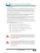
1 SAFETY Graphic Symbol Conventions Through out this User Guide these symbols will highlight information for your safety and the proper functioning of this equipment. Read carefully the steps in this guide and pay special attention to the steps where you see these symbols. NOTE Important information, tips, and hints are highlighted by the note graphic.
ELECTRICAL DANGER ALWAYS lock out and tag electrical circuit breakers while installing or servicing this equipment, pumps and related equipment. A potentially lethal electrical shock hazard and the possibility of an explosion or fire from a spark can result if the electrical circuit breakers are accidentally turned on during installation or servicing.
WARNING Allow no source of combustion near the work area. Be careful not to cause sparks when working on fuel dispensing equipment. Failure to follow these directions may cause an explosion hazard, which could result in property damage and death. WARNING These containment sumps can trap dangerous amounts of hydrocarbon vapors. If these vapors are inhaled they could cause dizziness or unconsciousness. If the vapors were ignited they could explode causing serious injury or death.
2 TS-TPI INSTALLATION & WIRING Overview The TS-TPI Turbine Pump Interface is a communication device that allows the INCON TS-1001, TS-2001 Automatic Tank Gauge (ATG) or other devices to communicate with the turbine pump controllers (TPC). The TS-TPI is available as a stand alone unit, which requires its own input power, and as an integrated factory installed option in the TS-LS300 AutoLearn Line Leak Detector.
TS-TPI specifications: Input power: 120 - 240 Vac 50/60 hz (note: stand alone TS-TPI only. the integrated TS-TPI/TSLS300 does not require any additional power connection to the TS-TPI) For indoor installation only, operating temperature 40 - 105° F (4 - 41° C) Use Belden Cable #9365 - 18 AWG or equivalent TS-TPI revision 2.3 or higher for use with MagVFC, STP-SCI, STP-SCIII, STP-SC, and IST-VFC controllers. Limited functions available with STP-SCIII, STP-SC and IST-VFC controllers.
Integrated TS-TPI / TS-LS300 to Automatic Tank Gauge TS-1001, TS2001 and TPCs ATG LS300 TPI BOARD TS1001 OR TS2001 ONLY TS-LLD INPUTS 485A 485B DSY S,RTN IN 1 GND IN 2 GND RED BLACK BLACK WHITE RED WHITE CABLE-BELDEN CONDUCTOR #9365-18AWG OR EQUIVALENT SEE TANK SENTINEL INSTALLATION GUIDE (PART # 000-150), LS300 USER'S GUIDE (PART # 000-0040), AND APPROPRIATE TPC INSTALLATION AND OWNER'S MANUAL FOR COMPLETE WIRING INFORMATION BLACK WHITE RED ADDITIONAL TPC GROUPS TXD 485GND RXD 485+ HOST PORT
TS-TPI / two TS-LS300 with Automatic Tank Gauge TS-1001, TS2001 ATG LS300 TPI BOARD TS1001 OR TS2001 ONLY TS-LLD INPUTS 485A 485B DSY S,RTN IN 1 GND IN 2 GND RED BLACK WHITE BLACK WHITE RED CABLE-BELDEN 3 CONDUCTOR #9365-18AWG OR EQUIVALENT SEE TANK SENTINEL INSTALLATION GUIDE (PART # 000-1050) AND LS300 USER'S GUIDE (PART # 000-0040) FOR COMPLETE ATG AND LS300 WIRING INFORMATION PURCHASE RS232 CABLE LOCALLY TXD 485GND RXD 485+ HOST PORT TXD 485GND RXD 485+ PORT 1 TXD 485GND RXD 485+ PORT 2
Wire diagram for TS-TPI with two TS-300 AutoLearn to Automatic Tank Gauge TS-1001, TS2001 and TPCs ATG LS300 TPI BOARD TS1001 OR TS2001 ONLY TS-LLD RED BLACK 485A 485B DSY S,RTN INPUTS WHITE IN 1 GND IN 2 GND BLACK WHITE RED CABLE-BELDEN 3 CONDUCTOR #9365-18AWG OR EQUIVALENT SEE TANK SENTINEL INSTALLATION GUIDE (PART # 000-1050) AND LS300 USER'S GUIDE (PART # 000-0040) FOR COMPLETE ATG AND LS300 WIRING INFORMATION ADDITIONAL TPC GROUPS TXD 485GND RXD 485+ HOST PORT TXD 485GND RXD 485+ PORT 1
Stand AloneTS-TPI with Automatic Tank Gauge TS-1001 or TS2001 and TPCs STAND ALONE TPI CABLE-BELDEN CONDUCTOR #9365-18AWG OR EQUIVALENT TPC BLACK WHITE RED RS485 +G PORT 4 TXD 485GND RXD 485+ PORT 2 PORT 1 PORT 3 TXD 485GND RXD 485+ SEE TANK SENTINEL INSTALLATION GUIDE (PART # 000-1050), THIS TPI USER'S GUIDE AND APPROPRIATE TPC INSTALLATION AND OWNER'S MANUAL FOR COMPLETE WIRING INFORMATION L1 120 -240 Vac 50/60 hz TXD 485GND RXD 485+ IN 1 GND IN 2 GND TPC FAULT RESET ALARM SILENCE GND L2/N
Stand AloneTS-TPI with TPCs STAND ALONE TS-TPI TXD 485GND RXD 485+ PORT 4 PORT 3 PORT 1 PORT 2 TXD 485GND RXD 485+ ALARM SILENCE L1 INPUT POWER TXD 485GND RXD 485+ TPC FAULT RESET TXD 485GND RXD 485+ Indoor installation only.
TPI Configuration Switch Locate the single dip switch on the TS-TPI board labeled SW1. This set of switches sets how the various ports communicate. The host (ATG) and Pump Controllers all communicate using RS-485 connections. The TS-LS300 communicates using RS232. The Factory default setting is switches 1, 2 and 3 are OFF and switch 4 is ON.
3 TANK SENTINEL/TS-TPI INTERFACE Overview The Turbine Pump Interface (TS-TPI) hardware has been developed to facilitate communications of the Turbine Pump Controllers (TPC) operating conditions with the INCON Tank Sentinel Automatic Tank Gauge (ATG) consoles via the RS-485 port. The integration of ATG, TS-TPI and TPC allows the ATG to intervene when pumps experience certain fault conditions by resolving the fault and enabling the pump to continue dispensing fuel.
In “Leveling Mode”, the ATG keeps the levels on multiple tanks the same and in the “Priority Mode”, a specified tank will draw down to its reserve percentage before other tanks are called upon. The ATG also performs tank level management by generating alarms to warn the operator of High and High High product limits, Low and Low Low product limits, water levels limits and even an obstruction on the pump motor.
Diagnostic Operations A pump controller Diagnostic menu is available on the console display to allow a user to reset a pump controller from the ATG. Another diagnostic function that is available is the ability to enable automatic calibration of the pump controller and its pumps. Remote Management The remote management feature allows an interface within System Sentinel or System Sentinel Anyware to acquire and display pump controller status.
4 TS-TPI SETUP PROGRAMMING TS-TPI Menu NOTE Prior to Enabling TPI, the System configuration for Number of Tanks is required. Refer to the Tank Sentinel Setup Programming Guide. H U MENU ½ 7 Press this key and follow the highlighted sequence below... TPI ENABLE (user entry) Description of Steps: SELECT MENU OPTION SETUP UPGRADE LANGUAGE DATALOG Here are the SELECT MENU OPTION menu names displayed. 1) Press the M1 key to display the SETUP menu.
TS-TPI PUMP Menu(s) NOTE Before preforming AUTO CFG verify all • AUTO CFG (user entry) TPCs dip switches are set correctly. If • NO PUMPS “READ ONLY” TPC switches are changed after AUTO CFG the ATG will need to be Cold • PUMP N Menus (both) Booted and the AUTO CFG procedure repeated. AUTO CFG (user entry) H Description of Steps: 1) Press the MENU key to display the SELECT MENU OPTION menu. U MENU 7 M1 2) Press the M1 key under the word SETUP to display the SETUP MENU menu.
AUTO-CONFIGURATION NOTE The AUTO CFG function is used to invoke the routines which query the TPI for the number of pump controllers attached to the TS-TPI and other controller and pump related information. When AUTO CFG is started, the tank gauge scans the TS-TPI for all the pump controllers attached to the TS-TPI. For each controller found, a corresponding pump number will be displayed (e.g. if the TS-TPI finds two controllers, there will be a Pump 1 and a Pump 2).
PUMP N Menu(s) • • • • • • NAME (user entry) TYPE “READ ONLY” GROUP “READ ONLY” ADDRESS “READ ONLY” TANK (user entry) HEIGHT (user entry) NAME (user entry) NOTE In the following examples, “N” represents any pump number - 1, 2, 3 and so on. Description of Steps: The PUMP N menu displays six subsequent fields, including TANK and HEIGHT (scroll down)... 1) Press the M1 key to display the NAME PUMP N user entry field... The default name of “PUMP 1 is displayed...
TYPE “READ ONLY” Description of Steps: PUMP N NAME 1) Press the M2 key to display the TYPE PUMP N “READ ONLY” field... In this example, the type “VFC” is displayed... There are five types of controller displays VFC, SC, SCIII, SCI and VFCIV. The displayed TYPE PUMP coresponds with the following FE Petro controllers: SC STP-SC SCI STP-SCI SCIII STP-SCIII VFC IST-VFC VFCIV MagVFC 2) Press the CANCEL key to return to the PUMP N menu.
ADDRESS “READ ONLY” Description of Steps: PUMP N NAME 1) Press the M4 key to display the ADDRESS PUMP N “READ ONLY” field... M1 TYPE GROUP M2 M3 ADDRESS PUMP 1 0 In this example, address “0” is displayed... The address range is from 0-31. (MORE) ADDRESS M4 READ ONLY 2) Press the CANCEL key to return to the PUMP CANCEL N menu. Press the DOWN key to display the TANK and HEIGHT user entry menus...
3) Press the ENTER key to accept data entry. The display returns to the PUMP N menu. Repeat the user entry steps for each pump. ENTER HEIGHT (user entry) 1) Press the M2 key to display the HEIGHT PUMP N user entry field... The default HEIGHT of “+7.0”(inches) is displayed... 2) Press the M4 key to backspace and erase the “+7.000000” default height number. PUMP N TANK M1 (MORE) HEIGHT M2 M3 HEIGHT PUMP 1 +7.
TPI Group Menu GROUP MENU NOTES • • • TYPE “READ ONLY” The Group menu is not available when pump controllers are not connected/programmed with the TS-TPI device. The Group menu name appears on the display but it does not function. MODE (user entry) RESERVE (user entry) Group 1 is removed from the display if one LS-300 is connected to the TS-TPI. Groups 1 and 2 are removed when two LS300s are connected. All Groups are displayed if zero LS-300s are connected.
MODE “User Entry” Note (Mode functions are not available with STP-SC, STP-SCIII or IST-VFC) MODE allows the operator to select which Level Management mode to use for a particular group. The choices are NONE, LEVELING, and PRIORITY: • Selecting NONE means NO level management mode for the Group (no Reserve to enter). This is used for Groups with TPCs configured as stand alone controllers.
RESERVE (user entry) Description of Steps: Here is the GROUP 2 main menu, displaying TYPE, MODE and RESERVE... 1) Press the M3 key to display the RESERVE menu... Here is the RESERVE user entry field displaying the “percent full” value for GROUP 2 (in Priority mode). The default setting is 20. 2) Press the M4 key to backspace and erase the default percent value. this will clear the field.
5 TPI AND LINE LEAK TESTING LN (Line) Test Menu H NOTE U MENU 7 ½ Press this key and follow the highlighted sequence below SELECT MENU OPTION SETUP UPGRADE LANGUAGE DATALOG Disregard this Chapter if the LN TESTS menu does not appear. Note that the position of this menu can be displaced by other menus. The LN TESTS and LINES menu, only appear if one or more NO. LINES are entered under the SYSTEM setup menu. SYSTEM INFO NO. LINES NO.
Line Leak Test Requirements & Notes: 1) Inform the Site Personnel to: (If the store closes at night - not 24-hour) Leave the Pump Controllers power on at night with dispenser power off. The Submerged Turbine Pump (STP) must be able to turn on to run the pressurized line leak tests. 2) It is recommended that Line Leak Tests and Tank Leak Tests should not be scheduled to run at the same time. 3) Note: The Monthly (0.
SUNDAY Press ENTER to accept this data. 1 ST DAY Dispensing during the test will abort the test* : 30 TH DAY NOTE: February does not have 30 days ! LAST DAY TIME 0.1 See Test Requirements and Notes ! 0.1 GPH LINE TEST TIME N 00:00:00 24 HOUR FORMAT See TABLE 5-1 Use Keypad to input 24-hour time data. Press ENTER to accept this data.
LN Line (leak) Tests Men u Menu * Only the No. of lines that are programmed in System menu are displayed FAIL OG Will go Active when any (3 gph, 0.2 gph, and 0.1 gph) LINE TEST FAIL OUTPUT GROUP Line Leak Test fails LINE 1 Press (M) key to select a LINE#. LINE 2 * : Use UP/DOWN ▲ ▼ keys to show more choices. * LINE 8 * LINE TEST FAIL OUTPUT GROUP N (32 Output Groups (OGs) available...See Tank Sentinal Setup Programming Guide, Worksheet 12-1) NONE Not assigned to an Output Group (OG).
6 TS-TPI DATA AND REPORTS Overview The INCON Tank Sentinel displays, prints and faxes data and report information for the user. This chapter describes the DISPLAY and DIAG (Diagnostic) menus, that feature comprehensive user-interface data and report functions. TPI Status Display Notes The Display function allows a user to view current information from pump controllers on a real time basis. The TPI periodically collects data from each pump controller.
Display Menu NOTE PUMPS (Data Display) “(Data Display)” means only data will appear in the display - there are no entries to make. Descriptions of Steps: “(User Interface)” means the user must make entries to implement the feature. 1) Press the MENU key and follow the highlighted sequences... The SELECT MENU OPTION menu is shown. H U MENU 7 SELECT MENU OPTION SETUP UPGRADE LANGUAGE K X DOWN SPACE 2) Press the DOWN key once... Here is the second SELECT MENU OPTION menu.
Pump DISPLAY examples: NOTE See Appendix A for Status Code Each controller type will vary in the available data that can be displayed. The example below is for the SCI controller. and Fault Code definitions. Here is the first display of three possible (typical) data displays... PUMP1 PUMP N STATUS 0071 FAULT 00 VOLTS 204 CVOLT 1 201 PUMP1 PUMP N AMPS 6.5 C AMPS1 6.5 WATTS 1140 C WATTS 1140 PUMP1 PUMP N DIPSW FFFB SREV 103 Press the DOWN key to scroll through the data displays.
TPI Diagnostic Function Notes The diagnostic function allows the user to command the pump controllers from the Tank Sentinel console. The user is able to issue resets to clear faults and enable calibration. To access this function, the user first presses the MENU key, then DIAG, then PUMPS and then PUMP #. The tank gauge allows the user to select a pump number and will then display the diagnostic function keys RESET and CALIBRT.
PUMP menu. SETUP MENU OPTION PUMPS The SELECT PUMP menu displays all of the pump numbers that are communicating with the Tank Sentinel. 5) Press the (M) key under each pump number to display the SELECT DIAGNOSTIC OPTION menu. In this example, Press the M1 key for the PUMP 1 options. M1 M2 SELECT PUMP PUMP 1 PUMP 2 M1 M2 M3 M4 (MORE) PUMP 4 PUMP 3 M3 M4 Here is the DIAGNOSTIC OPTION MENU.
CALIBRT Menu NOTE In the following examples, “N” represents any pump number 1, 2, 3 and so on. CALIBRT (User Interface) Description of Steps: Here is the SELECT DIAGNOSTIC OPTION menu displaying RESET and CALIBRT. SELECT DIAGNOSTIC OPTION RESET CALIBRT M1 M2 M3 M4 1) Press the M2 key under CALIBRT. The CALIBRATE PUMP N display asks if the user is sure before enabling automatic calibration for a particular pump controller; giving the user a chance to press CANCEL to abort the calibration process.
Pump Controller Status Report A Pump Status report indicates the current state of the pumps. This report is designed to facilitate troubleshooting at the site. This is the same information as found in the pump section of the programming and the DISPLAY pump status real time interface. The information can be polled and stored in System Sentinel or printed at the site by a technician when required. The following is a representation of a new pump controller status report.
How to print the report: Description of Steps: Here is the Tank Sentinel display in RUN MODE, showing SYSTEM, TANK, SENSOR, etc. are all OKAY... 1) Press the REPORT key to display the SELECT REPORT GROUP menu... 2) Press the DOWN key twice to show the PUMP menu selection... SYSTEM OKAY J TANK OKAY SENSOR OLAY LINE OKAY W REPORT 9 K W DOWN SPACE Here is the SELECT REPORT GROUP menu showing the PUMP menu selection... 3) Press the M1 key to display the PUMP STATUS REPORT selection menu...
System Setup Report Additions -- TPI TPI/Pump Controller Setup ENABLED YES ADDRESS 80 PUMP CONTROLLERS Tank Sentinel Setup reports show the entire configuration of the Tank Sentinel programming. NUMBER OF PUMPS 5 PUMP 1 NAME The TPI/Pump Controller section is located in the System Setup Report, below the Sensors section and above (before) the Cathodic Protection section.
Here is the SELECT SETUP REPORT display, showing SYSTEM, TANK, etc. ... 4) Press the M1 key to display the SYSTEM SETUP REPORT selection menu... SELECT SETUP REPORT SYSTEM TANK M1 Here is the SYSTEM SETUP REPORT display, showing two choices - PRINTER or FAX... PRINTER 5) Print the report to the console printer or via a fax-modem to a programmed fax telephone number. The Tank Sentinel display returns to the RUN MODE.
7 LINE Reports SETUP Reports Menu H U MENU 7 ½ Press this key in the highlighted sequence shown below SELECT MENU OPTION SETUP UPGRADE LANGUAGE M1 M2 SETUP MENU EXIT SYSTEM M3 DATALOG M4 (MORE) PROBES TANKS Press the DOWN ▼ key... SETUP MENU PRODUCTS MANIFOLDS* REPORTS M1 M2 M3 Use this menu to program reports to print or FAX automatically on a schedule (faxing requires an optional Fax/Modem device).
Reports Schedule Menu Line Compliance Report: The Line Compliance Report will include one year’s worth of 0.2 gph monthly compliance tests for a selected line, or all lines. The most recent test is shown first and the oldest test last. After a year, the oldest test will be dropped when a new test passes. Follow the following steps to schedule the line compliance report. All other line reports follow this same process. The rest of this section of the manual will only describe the report.
8 TROUBLESHOOTING This section is to aid in troubleshooting the TS-TPI and the integrated system that it is connected to. Two models of the TS-TPI are available, the factory installed option in the TS-LS300 AutoLearn and the TS-TPI stand alone unit. These troubleshooting steps will apply to both models unless otherwise indicated in the section. The TS-TPI has a number of LEDs as indicator lights to help communicate the status of the TS-TPI and the equipment it is connected to.
Status Codes During normal operation 21 TPC is ready to run, no hook signal is detected, and low priority 31 TPC is ready to run, a hook signal is detected, and low priority 61 TPC is ready to run, no hook signal is detected, and priority 71 TPC is ready to run, a hook signal is detected, and priority See chapter 3 “Level management” for details on “priority” and “low priority.” ● If the Status code is an even number this indicates the TPC is not detected by the TS-TPI.
STP-SCI or STP-SC HEXVALUE DECIMALVALUE 0 1 2 3 4 8 9 0 1 2 3 4 8 9 A 10 FAULT CODE DESCRIPTIONS No Fault Under Load (Dry Run or Tank Empty) Under Voltage (low / fluctuating input voltage) Locked Rotor Open Circuit (or Locked Rotor or Relay Fault) Uncalibrated (new installation) Extended Run (continuous hook signal greater than 60 minutes without pumping product) Relay Fault (relay contact failure) Controller STP-SCIII HEXVALUE DECIMALVALUE 0 1 2 3 4 8 9 0 1 2 3 4 8 9 A B C D E 10 11 12 13 14 MagVF
INSIDE BACK COVER TS-TPI Istallation and Wiring Guide
TS-TPI Turbine Pump Interface Installation and Wiring Guide