Submersible Motors Application • Installation • Maintenance 60 Hz, Single-Phase and Three-Phase Motors 2007
ATTENTION! IMPORTANT INFORMATION FOR INSTALLERS OF THIS EQUIPMENT! THIS EQUIPMENT IS INTENDED FOR INSTALLATION BY TECHNICALLY QUALIFIED PERSONNEL. FAILURE TO INSTALL IT IN COMPLIANCE WITH NATIONAL AND LOCAL ELECTRICAL CODES, AND WITHIN FRANKLIN ELECTRIC RECOMMENDATIONS, MAY RESULT IN ELECTRICAL SHOCK OR FIRE HAZARD, UNSATISFACTORY PERFORMANCE, AND EQUIPMENT FAILURE. FRANKLIN INSTALLATION INFORMATION IS AVAILABLE FROM PUMP MANUFACTURERS AND DISTRIBUTORS, AND DIRECTLY FROM FRANKLIN ELECTRIC.
Commitment to Quality Franklin Electric is committed to provide customers with defect free products through our program of continuous improvement. Quality shall, in every case, take precedence over quantity.
Submersible Motors Application • Installation • Maintenance Manual The submersible motor is a reliable, efficient and troublefree means of powering a pump. Its needs for a long operational life are simple. They are: 1. A suitable operating environment 2. An adequate supply of electricity 3. An adequate flow of cooling water over the motor 4.
Application – All Motors Storage Franklin Electric submersible motors are a waterlubricated design. The fill solution consists of a mixture of deionized water and Propylene Glycol (a non-toxic antifreeze). The solution will prevent damage from freezing in temperatures to -40 °F (-40 °C); motors should be stored in areas that do not go below this temperature. The solution will partially freeze below 27 °F (-3 °C), but no damage occurs.
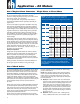
Application – All Motors Transformer Capacity - Single-Phase or Three-Phase Distribution transformers must be adequately sized to satisfy the kVA requirements of the submersible motor. When transformers are too small to supply the load, there is a reduction in voltage to the motor. Table 4 references the motor horsepower rating, singlephase and three-phase, total effective kVA required, and the smallest transformer required for open or closed three-phase systems.
Application – All Motors Use of Engine Driven Generators - Single-Phase or Three-Phase Table 5 lists minimum generator sizes based on typical 80 °C rise continuous duty generators, with 35% maximum voltage dip during starting, for Franklin’s threewire motors, single- or three-phase. This is a general chart. The generator manufacturer should be consulted whenever possible, especially on larger sizes. There are two types of generators available: externally and internally regulated.
Application – All Motors a zero head condition. This causes an uplifting or upthrust on the impeller-shaft assembly in the pump. This upward movement carries across the pumpmotor coupling and creates an upthrust condition in the motor. Repeated upthrust can cause premature failure of both the pump and the motor. the discharge piping.
Application – All Motors Head Loss From Flow Past Motor Table 7 lists the approximate head loss due to flow between an average length motor and smooth casing or flow inducer sleeve. Table 7 Head Loss in Feet (Meters) at Various Flow Rates MOTOR DIAMETER 4" 4" 4" 6" 6" 6" 8" 8" CASING ID IN INCHES (MM) 4 (102) 5 (127) 6 (152) 6 (152) 7 (178) 8 (203) 8.1 (206) 10 (254) Flow Rate in gpm (l/m) 25 (95) 0.3 (.09) 50 (189) 1.2 (.37) 100 (378) 4.7 (1.4) 0.3 (.09) 150 (568) 10.2 (3.1) 1.
Application – All Motors 2. Determine pump horsepower required from the pump manufacturer’s curve. Brake Horsepower 6 EXAMPLE 5 A B 4 C 3 2 1 0 0 5 10 15 20 25 30 35 40 45 50 Gallons Per Minute FIG. 2 MANUFACTURER’S PUMP CURVE Table 8 Heat Factor Multiplier at 3 ft/s (.91 m/sec) Flow Rate 3. Multiply the pump horsepower required by the heat factor multiplier from table 8. MAXIMUM WATER TEMPERATURE 1/3 - 5 HP .25 - 3.7 KW 7 1/2 - 30 HP 5.
Application – All Motors Drawdown Seals Allowable motor temperature is based on atmospheric pressure or higher surrounding the motor. “Drawdown seals,” which seal the well to the pump above its intake to maximize delivery, are not recommended, since the suction created can be lower than atmospheric pressure. Grounding Control Boxes and Panels The National Electrical Code requires that the control box or panel-grounding terminal always be connected to supply ground.
Application – Single-Phase Motors 3-Wire Control Boxes Single-phase three-wire submersible motors require the use of control boxes. Operation of motors without control boxes or with incorrect boxes can result in motor failure and voids warranty. Control boxes contain starting capacitors, a starting relay, and, in some sizes, overload protectors, running capacitors and contactors.
Application – Single-Phase Motors 2 or 3-Wire Cable, 60 Hz (Service Entrance to Motor - Maximum Length In Feet) 60 °C Table 11 MOTOR RATING 60 °C INSULATION - AWG COPPER WIRE SIZE VOLTS HP KW 14 12 10 8 6 4 3 2 1 0 00 000 0000 115 1/2 .37 100 160 250 390 620 960 1190 1460 1780 2160 2630 3140 3770 1/2 .37 400 650 1020 1610 2510 3880 4810 5880 7170 8720 3/4 .55 300 480 760 1200 1870 2890 3580 4370 5330 6470 7870 1 .
Application – Single-Phase Motors Two or More Different Cable Sizes Can Be Used occurs in this wire. This leaves us 46.7% (1.00 - 0.533 = 0.467) of some other wire size to use in the remaining 310 feet “down hole” wire run. Depending on the installation, any number of combinations of cable may be used. For example, in a replacement/upgrade installation, the well already has 160 feet of buried #10 cable between the service entrance and the wellhead.
Application – Single-Phase Motors Table 13 Single-Phase Motor Specifications (60 Hz) 3450 rpm FULL LOAD MAXIMUM (S.F. LOAD) (2) WATTS AMPS 12.0 960 6.0 960 8.0 1310 9.8 1600 13.1 2180 Y12.0 B12.0 960 R0 Y6.0 B6.0 960 R0 Y8.0 B8.0 1310 R0 Y9.8 B9.8 1600 R0 HP KW VOLTS HZ S.F. 244504 244505 244507 244508 244309 1/2 1/2 3/4 1 1.5 0.37 0.37 0.55 0.75 1.1 115 230 230 230 230 60 60 60 60 60 1.6 1.6 1.5 1.4 1.3 214504 1/2 0.37 115 60 1.6 214505 1/2 0.37 230 60 1.6 214507 3/4 0.
Application – Single-Phase Motors Table 14 Single-Phase Motor Fuse Sizing 4" 3-WIRE W/CRC CB 4" 3-WIRE 4" 2-WIRE TYPE MOTOR MODEL PREFIX CIRCUIT BREAKERS OR FUSE AMPS CIRCUIT BREAKERS OR FUSE AMPS (MAXIMUM PER NEC) (TYPICAL SUBMERSIBLE) RATING HP KW VOLTS STANDARD FUSE DUAL ELEMENT TIME DELAY FUSE CIRCUIT BREAKER STANDARD FUSE DUAL ELEMENT TIME DELAY FUSE CIRCUIT BREAKER 244504 1/2 0.37 115 35 20 30 30 15 30 244505 1/2 0.37 230 20 10 15 15 8 15 244507 3/4 0.
Application – Single-Phase Motors Auxiliary Running Capacitors Although motor amps decrease when auxiliary run capacitance is added, the load on the motor does not. If a motor is overloaded with normal capacitance, it still will be overloaded with auxiliary run capacitance, even though motor amps may be within nameplate values. Added capacitors must be connected across “Red” and “Black” control box terminals, in parallel with any existing running capacitors.
Application – Three-Phase Motors Table 16 Three-Phase 60 °C Cable, 60 Hz (Service Entrance to Motor) Maximum Length in Feet MOTOR RATING VOLTS 200 V 60 Hz ThreePhase 3 - Lead 230 V 60 Hz ThreePhase 3 - Lead 380 V 60 Hz ThreePhase 3 - Lead 60 °C INSULATION - AWG COPPER WIRE SIZE HP KW 14 12 10 8 6 4 3 1/2 0.37 710 1140 1800 2840 4420 3/4 0.55 510 810 1280 2030 3160 1 0.75 430 690 1080 1710 1.5 1.1 310 500 790 1260 2670 4140 5140 1960 3050 2 1.
Application – Three-Phase Motors 60 °C Table 17 Three-Phase 60 °C Cable (Continued) MOTOR RATING VOLTS 460 V 60 Hz ThreePhase 3 - Lead 575 V 60 Hz ThreePhase 3 - Lead 60 °C INSULATION - AWG COPPER WIRE SIZE HP KW 14 12 10 8 6 4 1/2 0.37 3770 6020 9460 3/4 0.55 2730 4350 6850 1 0.75 2300 3670 5770 9070 1.5 1.1 1700 2710 4270 6730 2 1.5 1300 2070 3270 5150 8050 3 2.2 1000 1600 2520 3970 6200 5 3.7 590 950 1500 2360 3700 5750 7.5 5.
Application – Three-Phase Motors 60 °C Table 18 Three-Phase 60 °C Cable (Continued) MOTOR RATING VOLTS HP KW 5 3.7 200 V 7.5 5.5 60 Hz 10 7.5 Three15 11 Phase 20 15 6 - Lead 25 18.5 Y-D 30 22 5 3.7 230 V 7.5 5.5 60 Hz 10 7.5 Three15 11 Phase 20 15 6 - Lead 25 18.5 Y-D 30 22 5 3.7 7.5 5.5 10 7.5 15 11 20 15 25 18.5 380 V 30 22 60 Hz 40 30 ThreePhase 50 37 6 - Lead 60 45 Y-D 75 55 100 75 125 90 150 110 175 130 200 150 5 3.7 7.5 5.5 10 7.5 15 11 20 15 25 18.
Application – Three-Phase Motors Table 19 Three-Phase 75 °C Cable, 60 Hz (Service Entrance to Motor) Maximum Length in Feet MOTOR RATING VOLTS 200 V 60 Hz ThreePhase 3 - Lead 230 V 60 Hz ThreePhase 3 - Lead 380 V 60 Hz ThreePhase 3 - Lead 75 °C INSULATION - AWG COPPER WIRE SIZE HP KW 14 12 10 8 6 1/2 0.37 710 1140 1800 2840 4420 3/4 0.55 510 810 1280 2030 3160 690 1080 1710 4 3 75 °C MCM COPPER WIRE SIZE 2 1 0 00 000 0000 250 300 350 400 500 1 0.
Application – Three-Phase Motors 75 °C Table 20 Three-Phase 75 °C Cable (Continued) MOTOR RATING VOLTS 460 V 60 Hz ThreePhase 3 - Lead 575 V 60 Hz ThreePhase 3 - Lead 75 °C INSULATION - AWG COPPER WIRE SIZE HP KW 14 12 10 1/2 0.37 3770 6020 9460 3/4 0.55 2730 4350 6850 3670 8 6 4 3 2 1 MCM COPPER WIRE SIZE 0 00 000 7110 0000 250 300 350 400 500 1 0.75 2300 5770 9070 1.5 1.1 1700 2710 4270 6730 2 1.5 1300 2070 3270 5150 8050 3 2.
Application – Three-Phase Motors 75 °C Table 21 Three-Phase 75 °C Cable (Continued) MOTOR RATING VOLTS HP KW 5 3.7 200 V 7.5 5.5 60 Hz 10 7.5 Three15 11 Phase 20 15 6 - Lead 25 18.5 Y-D 30 22 5 3.7 230 V 7.5 5.5 60 Hz 10 7.5 Three15 11 Phase 20 15 6 - Lead 25 18.5 Y-D 30 22 5 3.7 7.5 5.5 10 7.5 15 11 20 15 25 18.5 380 V 30 22 60 Hz 40 30 ThreePhase 50 37 6 - Lead 60 45 Y-D 75 55 100 75 125 90 150 110 175 130 200 150 5 3.7 7.5 5.5 10 7.5 15 11 20 15 25 18.
Application – Three-Phase Motors Table 22 Three-Phase Motor Specifications (60 Hz) TYPE 4" MAXIMUM (S.F. LOAD) MOTOR MODEL PREFIX HP KW VOLTS HZ S.F. AMPS WATTS AMPS WATTS LINE TO LINE RESISTANCE OHMS F.L. LOCKED ROTOR AMPS KVA CODE S.F. 234501 1/2 0.37 200 60 1.6 2.8 585 3.4 860 6.6-8.4 70 234511 1/2 0.37 230 60 1.6 2.4 585 2.9 860 9.5-10.9 70 64 17.5 N 64 15.2 234541 1/2 0.37 380 60 1.6 1.4 585 2.1 860 23.2-28.6 N 70 64 9.2 N 234521 1/2 0.
Application – Three-Phase Motors Table 23 Three-Phase Motor Fuse Sizing TYPE 4" 23 MOTOR MODEL PREFIX CIRCUIT BREAKERS OR FUSE AMPS CIRCUIT BREAKERS OR FUSE AMPS (MAXIMUM PER NEC) (TYPICAL SUBMERSIBLE) RATING HP KW VOLTS STANDARD FUSE DUAL ELEMENT TIME DELAY FUSE CIRCUIT BREAKER STANDARD FUSE DUAL ELEMENT TIME DELAY FUSE CIRCUIT BREAKER 234501 1/2 0.37 200 234511 1/2 0.37 230 10 5 8 8 4.5 6 10 4 15 8 4 234541 1/2 0.37 380 5 2.5 15 4 5 2 234521 1/2 0.
Application – Three-Phase Motors Table 24 Three-Phase Motor Specifications (60 Hz) TYPE 6" MAXIMUM (S.F. LOAD) MOTOR MODEL PREFIX HP KW VOLTS HZ S.F. AMPS WATTS AMPS WATTS LINE TO LINE RESISTANCE OHMS F.L. LOCKED ROTOR AMPS KVA CODE S.F. 236650 5 3.7 200 60 1.15 17.5 4700 20.0 5400 .77-.93 79 236600 5 3.7 230 60 1.15 15 4700 17.6 5400 1.0-1.2 79 79 99 H 79 86 236660 5 3.7 380 60 1.15 9.1 4700 10.7 5400 2.6-3.2 H 79 79 52 236610 5 3.
Application – Three-Phase Motors Table 25 Three-Phase Motor Fuse Sizing TYPE 6" 25 MOTOR MODEL PREFIX CIRCUIT BREAKERS OR FUSE AMPS CIRCUIT BREAKERS OR FUSE AMPS (MAXIMUM PER NEC) (TYPICAL SUBMERSIBLE) RATING HP KW VOLTS STANDARD FUSE DUAL ELEMENT TIME DELAY FUSE CIRCUIT BREAKER STANDARD FUSE DUAL ELEMENT TIME DELAY FUSE CIRCUIT BREAKER 236650 5 3.7 200 60 35 45 50 25 45 236600 5 3.7 230 45 30 40 45 20 40 236660 5 3.7 380 30 17.5 25 30 12 25 236610 5 3.
Application – Three-Phase Motors Table 26 Three-Phase Motor Specifications (60 Hz) TYPE 8" MAXIMUM (S.F. LOAD) MOTOR MODEL PREFIX HP KW VOLTS HZ S.F. AMPS KILOWATTS AMPS 239660 40 30 380 60 1.15 64 35 72 239600 40 30 460 60 1.15 53 35 239610 40 30 575 60 1.15 42 239661 50 37 380 60 1.15 239601 50 37 460 60 239611 50 37 575 239662 60 45 380 239602 60 45 239612 60 239663 EFFICIENCY % KILOWATTS LINE TO LINE RESISTANCE OHMS F.L.
Application – Three-Phase Motors Table 27 Three-Phase Motor Fuse Sizing TYPE 8" 27 MOTOR MODEL PREFIX CIRCUIT BREAKERS OR FUSE AMPS RATING CIRCUIT BREAKERS OR FUSE AMPS (MAXIMUM PER NEC) (TYPICAL SUBMERSIBLE) HP KW VOLTS STANDARD FUSE DUAL ELEMENT TIME DELAY FUSE CIRCUIT BREAKER STANDARD FUSE DUAL ELEMENT TIME DELAY FUSE CIRCUIT BREAKER 239660 40 30 380 200 125 175 200 80 175 239600 40 30 460 175 100 150 175 70 150 239610 40 30 575 150 80 110 125 60 110 239661
Application – Three-Phase Motors Overload Protection of Three-Phase Submersible Motors The characteristics of submersible motors are different than standard motors and special overload protection is required. Class 10 Protection Required All heaters and amp settings shown are based on total line amps. When determining amperage settings or making heater selections for a six-lead motor with a Wye-Delta starter, divide motor amps by 1.732.
Application – Three-Phase Motors Table 29 - 60 Hz 6" Motors HP 5 7.5 10 15 20 25 30 40 50 60 29 KW 3.7 5.5 7.5 11 15 18.5 22 30 37 45 VOLTS NEMA STARTER SIZE 200 HEATERS FOR OVERLOAD RELAYS ADJUSTABLE RELAYS (NOTE 3) FURNAS (NOTE 1) G.E. (NOTE 2) SET MAX. 1 K61 L220B 17.6 19.1 230 1 K61 L199B 15.4 16.6 380 0 K52 L122B 9.4 10.1 460 0 K49 L100B 7.7 8.3 575 0 K42 L825A 6.1 6.6 200 1 K67 L322B 26.3 28.3 230 1 K64 L293B 22.9 24.
Submersible Pump Installation Check List 1. Motor Inspection ❑ ❑ ❑ ❑ A. Verify that the model, hp or kW, voltage, phase and hertz on the motor nameplate match the installation requirements. B. Check that the motor lead assembly is not damaged. C. Measure insulation resistance using a 500 or 1000 volt DC megohmmeter from each lead wire to the motor frame. Resistance should be at least 200 megohms without drop cable. D. Keep a record of motor model number, hp or kW, voltage, and serial number (S/N).
Submersible Pump Installation Check List ❑ F. Check insulation resistance as pump/motor assembly is lowered into the well. Resistance may drop gradually as more cable enters the water, but any sudden drop indicates possible cable, splice or motor lead damage; see page 44. 9. After Installation ❑ ❑ ❑ ❑ ❑ A. Check all electrical and water line connections and parts before starting the pump. B. Start the pump and check motor amps and pump delivery.
Submersible Motor Installation Record RMA No.
Submersible Motor Installation Record Power Supply: Cable: Service Entrance to Control ____________ft_______ AWG/MCM Cable: Control to Motor ____________ft________ AWG/MCM ❑ Copper ❑ Jacketed ❑ Copper ❑ Jacketed PUMP PANEL ❑ Aluminum ❑ Individual Conductors ❑ Aluminum ❑ Individual Conductors P U M P SERVICE ENTRANCE M O T O R Transformers: kVA __________ #1 __________ #2 __________ #3 Initial Megs (motor & lead) T1________T2_______T3________ Control Panel: Final Megs (motor, lead & cable) T1______T2__
Submersible Motor Booster Installation Record Submersible Motor Booster Installation Record Date ______ /______/_______ Filled In By _______________________________ RMA No.
Submersible Motor Booster Installation Record Insulation Check: Initial Megs: Motor & Lead Only Black (T1/U1)_________ Yellow (T2/V1)________ Red (T3/W1)_________ Installed Megs: Motor, Lead, & Cable Black (T1/U1)_________ Yellow (T2/V1)________ Red (T3/W1)_________ Voltage To Motor: Non-Operating: B-Y (T1/U1 - T2/V1)_____ Y-R (T2/V1 - T3/W1)_____ R-B (T3/W1 - T1/U1)_____ At Rated Flow of __________gpm B-Y (T1/U1 - T2/V1)_____ Y-R (T2/V1 - T3/W1)_____ R-B (T3/W1 - T1/U1)_____ At Open Flow __________
Application – Three-Phase Motors Recommended Adjustable Overload Relays Advance Controls: MDR3 Overload Table 30 - 60 Hz 8" Motors AEG Series: B17S, B27S, B27-2 ABB Type: RVH 40, RVH65, RVP160, T25DU, T25CT, TA25DU AGUT: MT03, R1K1, R1L0, R1L3, TE set Class 5 Allen Bradley: Bulletin 193, SMP-Class 10 only Automatic Switch Types: DQ, LR1-D, LR1-F, LR2 Class 10 HP 40 50 KW 30 37 Benshaw: RSD6 (Class 10) Soft Start Bharita C-H: MC 305 ANA 3 Clipsal: 6CTR, 6MTR Cutler-Hammer: C316F, C316P, C316S, C310-
Application – Three-Phase Motors SubMonitor Three-Phase Protection Applications SubMonitor is designed to protect 3-phase pumps/ motors with service factor amp ratings (SFA) from 5 to 350 A (approx. 3 to 200 hp). Current, voltage, and motor temperature are monitored using all three legs and allows the user to set up the SubMonitor quickly and easily.
Application – Three-Phase Motors Three-Phase Starter Diagrams Three-phase combination magnetic starters have two distinct circuits: a power circuit and a control circuit. The power circuit consists of a circuit breaker or fused line switch, contacts, and overload heaters connecting incoming power lines L1, L2, L3 and the three-phase motor. The control circuit consists of the magnetic coil, overload contacts and a control device such as a pressure switch.
Application – Three-Phase Motors Three-Phase Power Unbalance A full three-phase supply is recommended for all threephase motors, consisting of three individual transformers or one three-phase transformer. So-called “open” delta or wye connections using only two transformers can be used, but are more likely to cause problems, such as FIG. 10 FULL THREE-PHASE poor performance, overload tripping or early motor failure due to current unbalance.
Application – Three-Phase Motors Three-Phase Motor Lead Identification Line Connections — Six-Lead Motors T5-V2 (YELLOW) WARNING: When installing 6-lead motors extra care must be used to ensure lead identification at the surface. Leads must be marked and connected per diagram. Motor leads are not connected red to red, yellow to yellow, etc.
Application – Three-Phase Motors Reduced Voltage Starters All Franklin three-phase submersible motors are suitable for full-voltage starting. Under this condition the motor speed goes from zero to full speed within a half second or less. The motor current goes from zero to locked rotor amps, then drops to running amps at full speed. This may dim lights, cause momentary voltage dips to other electrical equipment, and shock power distribution transformers.
Application – Three-Phase Motors Inline Booster Pump Systems (continued) water must be done by an approved Franklin service shop or representative using a vacuum fill system per Franklin’s Motor Service Manual instruction. The motor shell then must be permanently stamped with a D closely behind the Serial Number. Design And Operational Requirements 1.
Application – Three-Phase Motors Inline Booster Pump Systems (continued) 9. Controls-Soft Starters and VFDs: Reduced voltage starters and variable speed drives (inverter drives) may be used with Franklin three-phase submersible motors to reduce starting current, upthrust, and mechanical stress during start-up. The guidelines for their use with submersible motors are different than with normal air cooled motor applications.
Application – Three-Phase Motors Inline Booster Pump Systems (continued) 17. Open Atmosphere Booster Pump Systems: When an open booster is placed in a lake, tank, etc. that is open to atmospheric pressure, the water level must provide sufficient head pressure to allow the pump to operate above its NPSHR requirement at all times and all seasons. Adequate inlet pressure must be provided prior to booster start-up.
Application – Three-Phase Motors Variable Speed Submersible Pump Operation, Inverter Drives Franklin three-phase submersible motors are operable from variable frequency inverter drives when applied within guidelines below. These guidelines are based on present Franklin information for inverter drives, lab tests and actual installations, and must be followed for warranty to apply. Franklin two-wire and three-wire single-phase submersible motors are not recommended for variable speed operation.
Installation – All Motors 4” Super Stainless — Dimensions 4” High Thrust — Dimensions (Standard Water Well) (Standard Water Well) 1.48" MAX 0.030" R MAX 0.50" MIN. FULL SPLINE 0.030" R MAX 1.508" 1.498" 5/16 - 24 UNF-2A MOUNTING STUDS 0.50" MIN. FULL SPLINE 1.508" 1.498" 5/16 - 24 UNF-2A MOUNTING STUDS 0.97" 0.79" 0.161" MAX LEAD BOSS HEIGHT 1.48" MAX 1.09" 0.91" 0.161" MAX LEAD BOSS HEIGHT 3.75" DIA. 3.75" DIA.
Installation – All Motors Tightening Motor Lead Connector Jam Nut 4" Motors: 15 to 20 ft-lb (20 to 27 Nm) 6" Motors: 50 to 60 ft-lb (68 to 81 Nm) 8" Motors with 1-3/16” to 1-5/8” Jam Nut: 50 to 60 ft-lb (68 to 81 Nm) 8" Motors with 4 Screw Clamp Plate: Apply increasing torque to the screws equally in a criss-cross pattern until 80 to 90 in-lb (9.0 to 10.2 Nm) is reached. first few hours after assembly may reduce the jam nut torque.
Maintenance – All Motors System Troubleshooting Motor Does Not Start POSSIBLE CAUSE CHECKING PROCEDURES CORRECTIVE ACTION A. No power or incorrect voltage. Check voltage at line terminals. The voltage must be ± 10% of rated voltage. Contact power company if voltage is incorrect. B. Fuses blown or circuit breakers tripped. Check fuses for recommended size and check for loose, dirty or corroded connections in fuse receptacle. Check for tripped circuit breakers.
Maintenance – All Motors System Troubleshooting Motor Runs Continuously POSSIBLE CAUSE CHECKING PROCEDURES CORRECTIVE ACTION A. Pressure switch. Check switch for welded contacts. Check switch adjustments. Clean contacts, replace switch, or adjust setting. B. Low water level in well. Pump may exceed well capacity. Shut off pump, wait for well to recover. Check static and drawdown level from well head. Throttle pump output or reset pump to lower level. Do not lower if sand may clog pump. C.
Maintenance – All Motors Table 44 Preliminary Tests - All Sizes Single- and Three-Phase “TEST” PROCEDURE WHAT IT MEANS 1. If the ohms value is normal (table 45), the motor is not grounded and the cable insulation is not damaged. 1. Open master breaker and disconnect all leads from control box or pressure switch (QD type control, remove lid) to avoid electric shock hazard and damage to the meter. 2. If the ohms value is below normal, either the windings are grounded or the cable insulation is damaged.
Maintenance – All Motors Insulation Resistance Readings Table 45 Normal ohm and Megohm Values Between All Leads and Ground CONDITION OF MOTOR AND LEADS OHMS VALUE MEGOHM VALUE A new motor (without drop cable). 200,000,000 (or more) 200.0 (or more) A used motor which can be reinstalled in well. 10,000,000 (or more) 10.0 (or more) 2,000,000 (or more) 2.0 (or more) 500,000 - 2,000,000 0.50 - 2.0 Less than 500,000 Less than .50 MOTOR IN WELL. READINGS ARE FOR DROP CABLE PLUS MOTOR. New motor.
Maintenance – Single-Phase Motors & Controls Identification Of Cables When Color Code Is Unknown (Single-Phase 3-Wire Units) If the colors on the individual drop cables cannot be found with an Ohmmeter, measure: Cable 1 to Cable 2 Cable 2 to Cable 3 Cable 3 to Cable 1 Find the highest resistance reading. The lead not used in the highest reading is the yellow lead. Use the yellow lead and each of the other two leads to get two readings: Highest is the red lead. Lowest is the black lead.
Maintenance – Single-Phase Motors & Controls Ohmmeter Tests QD, Solid State Control Box (Power Off) A. START CAPACITOR AND RUN CAPACITOR IF APPLICABLE (CRC) C. POTENTIAL (VOLTAGE) RELAY Step 1. Coil Test 1. Meter Setting: R x 1,000. 1. Meter setting: R x 1,000. 2. Connections: Capacitor terminals. 2. Connections: #2 & #5. 3. Correct meter reading: Pointer should swing toward zero, then back to infinity. 3. Correct meter readings: B. Q.D. (BLUE) RELAY Step 1. Triac Test 1. Meter setting: R x 1,000.
Maintenance – Single-Phase Motors & Controls Table 48 QD Control Box Parts 60 Hz HP 1/3 1/2 3/4 1 VOLTS CONTROL BOX MODEL NUMBER QD (BLUE) RELAY START CAPACITOR MFD VOLTS 115 280 102 4915 223 415 905 275 464 125 159-191 110 230 280 103 4915 223 415 901 275 464 126 43-53 220 115 280 104 4915 223 415 906 275 464 201 250-300 125 230 280 105 4915 223 415 902 275 464 105 59-71 220 230 282 405 5015 (CRC) 223 415 912 275 464 126 43-53 220 230 280 107 4915 223 415 903 275
Maintenance – Single-Phase Motors & Controls Table 49 Integral Horsepower Control Box Parts 60 Hz MOTOR SIZE MOTOR RATING HP 4" 1 - 1.5 STANDARD CONTROL BOX (1) MODEL NO. CAPACITORS OVERLOAD (2) PART NO. RELAY (3) PART NO. 1 1 275 411 107 155 031 102 220 370 1 1 None (See Note 4) 155 031 102 PART NO. (2) MFD. VOLTS QTY.
Maintenance – Single-Phase Motors & Controls Table 50 Integral hp Capacitor Replacement Kits CAPACITOR NUMBER KIT 275 463 122 305 206 912 275 463 111 305 206 911 275 463 120 305 206 920 275 464 113 305 207 913 275 468 117 305 208 917 275 468 118 305 208 918 275 468 119 305 208 919 275 468 120 305 208 920 155 327 101 305 203 901 155 327 102 305 203 902 155 327 109 305 203 909 155 327 114 305 203 914 155 328 101 305 204 901 155 328 102 305 204 902 155 328 103 305 204 903 Tabl
– Single-Phase Motors & Controls Maintenance Control Box Wiring Diagrams GND GND ORANGE CAP QD RELAY BLUE YELLOW Y (MOTOR LEADS) L2 CAP QD RELAY B BLUE L1 RED RED BLACK B (MAIN) L1 (LINE LEADS) YELLOW Y (MOTOR LEADS) R (START) L2 (LINE LEADS) START CAPACITOR RUN CAPACITOR GND 1/2 - 1 hp CRC QD RELAY 282 40_ 5015 Sixth digit depends on hp GREEN BLUE ORANGE R (START) RUN CAPACITOR GREEN START CAPACITOR B (MAIN) GND 1/3 - 1 hp QD RELAY 280 10_ 4915 Sixth digit depends on hp GR
Maintenance – Single-Phase Motors & Controls START CAPACITOR RUN CAPACITOR START CAPACITOR RUN CAPACITOR BLK BLK L2 L1 ORG T1 YEL 2 RED BLK RED YEL COIL 5 BLK YEL LINE CONTACTOR BLK RED ORG YEL T2 YEL 5 RELAY RELAY 1 RED 2 1 BLU BLK YEL LINE POWER FROM TWO POLE FUSED SWITCH OR CIRCUIT BREAKER, AND OTHER CONTROL IF USED.
– Single-Phase Motors & Controls Maintenance START CAPACITOR BLK START CAPACITOR BLK RUN CAPACITOR RUN CAPACITOR BLK BLK RED BLK RED RED RED T2 L2 YEL LINE CONTACTOR BLK BLK COIL COIL ORG YEL 5 RELAY T1 L1 RED 2 1 BLK BLK ORG YEL YEL YEL 5 RELAY L1 YEL L2 GROUND LEAD RED BLK L1 SW L2 BLK RED YEL BLK RED YEL GROUND LEAD RED 2 1 YEL RED BLK BLK 1 2 2 1 START OVERLOAD MAIN OVERLOAD GROUND TO LEAD MOTOR LINE POWER FROM TWO POLE FUSED SWITCH OR CIRCUIT BRE
Maintenance – Single-Phase Motors & Controls START CAPACITOR START CAPACITOR START CAPACITOR START CAPACITOR BLK BLK ORG ORG BLK ORG BLK ORG START CAPACITOR BLK RUN CAPACITOR BLK BLK RED RED BLK RUN CAPACITOR YEL YEL T2 L2 LINE CONTACTOR BLK BLK COIL COIL BLK YEL 5 BLK T1 L1 RELAY 1 RED 2 RELAY 1 YEL BLK RED RED GROUND LEAD BLK 1 2 MAIN OVERLOAD GROUND LEAD START OVERLOAD TO MOTOR LINE POWER FROM TWO POLE FUSED SWITCH OR CIRCUIT BREAKER 10 hp STANDARD 282 202
Maintenance – Electronic Products Pumptec-Plus Pumptec-Plus is a pump/motor protection device designed to work on any 230 V single-phase induction motor (PSC, CSCR, CSIR, and split phase) ranging in size from 1/2 to 5 horsepower. Pumptec-Plus uses a micro-computer to continuously monitor motor power and line voltage to provide protection against dry well, water logged tank, high and low voltage and mud or sand clogging.
Maintenance – Electronic Products Pumptec-Plus Pumptec-Plus - Troubleshooting SYMPTOM After Installation POSSIBLE CAUSE SOLUTION Dry Well Wait for the automatic restart timer to time out. During the time out period the well should recover and fill with water. If the automatic reset timer is set to the manual position, then the reset button must be pressed to reactivate the unit. Blocked Intake Solid Yellow Light Blocked Discharge Remove blockage in plumbing. Check Valve Stuck Replace check valve.
Maintenance – Electronic Products QD Pumptec and Pumptec QD Pumptec and Pumptec are load sensing devices that monitor the load on submersible pumps/motors. If the load drops below a preset level for a minimum of 4 seconds the QD Pumptec or the Pumptec will shut off the motor. The QD Pumptec is designed and calibrated expressly for use on Franklin Electric 230 V 3-wire motors (1/3 to 1 hp.) The QD Pumptec must be installed in QD relay boxes.
Maintenance – Electronic Products SubDrive75, 150, 300, MonoDrive, & MonoDrive XT The Franklin Electric SubDrive/MonoDrive Constant Pressure controller is a variable-speed drive that delivers water at a constant pressure. WARNING: Serious or fatal electrical shock may result from failure to connect the motor, SubDrive/MonoDrive Controller, metal plumbing and all other metal near the motor or cable to the power supply ground terminal using wire no smaller than motor cable wires.
Maintenance – Electronic Products SubMonitor SubMonitor Troubleshooting FAULT MESSAGE SF Amps Set Too High Phase Reversal PROBLEM/CONDITION SF Amps setting above 359 Amps. Motor SF Amps not entered. Reversed incoming voltage phase sequence. Incoming power problem. Normal line current. Wrong SF Max Amps setting. Low line current. Over pumping well. Clogged pump intake. Closed valve. Loose pump impeller. Broken shaft or coupling. Phase loss. Normal line current. Wrong SF Max Amps setting.
Maintenance – Electronic Products Subtrol-Plus (Obsolete - See SubMonitor) Subtrol-Plus - Troubleshooting After Installation SYMPTOM Subtrol-Plus Dead POSSIBLE CAUSE OR SOLUTION When the Subtrol-Plus reset button is depressed and released, all indicator lights should flash. If line voltage is correct at the Subtrol-Plus L1, L2, L3 terminals and the reset button does not cause lights to flash, Subtrol-Plus receiver is malfunctioning.
Maintenance – Electronic Products Subtrol-Plus (Obsolete - See SubMonitor) Subtrol-Plus - Troubleshooting After Installation (Continued) SYMPTOM Tripped Light On Control Circuit Fuse Blows Contactor Will Not Close POSSIBLE CAUSE OR SOLUTION Whenever the pump is off as a result of Subtrol-Plus protective function, the red tripped light is on.
Abbreviations A Amp or amperage MCM Thousand Circular Mils AWG American Wire Gauge mm Millimeter BJT Bipolar Junction Transistor MOV Metal Oxide Varister °C Degree Celsius NEC National Electrical Code CB Control Box NEMA CRC Capacitor Run Control National Electrical Manufacturer Association DI Deionized Nm Newton Meter Dv/dt Rise Time of the Voltage NPSH Net Positive Suction Head EFF Efficiency OD Outside Diameter °F Degree Fahrenheit OL Overload FDA Federal Drug Admin
Notes
Notes
Notes
TOLL FREE HELP FROM A FRIEND 800-348-2420 • 260-827-5102 (fax) Phone Franklin’s toll free SERVICE HOTLINE for answers to your pump and motor installation questions. When you call, a Franklin expert will offer assistance in troubleshooting and provide immediate answers to your system application questions. Technical support is also available online. Visit our website at: www.franklin-electric.