
Operating Manual


Fredenstein Bento 10S Module Carrier
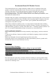
Front View:
Operation:
After installation of the modules, connect the mains cord to the Bento 10S IEC socket located on
the back-panel and than connect the mains cable to a grounded outlet. Now turn the Bento 10S on
by operating the I/O switch (also part of the IEC socket on the back). The five LEDs on the front-
panel will come on within 5 seconds and the Bento 10S is ready for use.
In case you want, for example, route the audio signal from a mic-pre in slot 1 to an EQ in slot 2 and
then to a compressor in slot 3, turn the switches located in the lower part of the back-panel between
the slot 1 and 2 and slot 2 and 3 in the link position. (Please be aware that this disables the slot 2
and the slot 3 input XLR connectors). Slot 1 input will be the microphone input and the slot 3
output will be the audio output of the complete chain.
If you are using multiple compressors which make use of the compressor link buss (Pin 6), you can
link two adjacent slots by putting the buss switch in the I position. You have the flexibility to have
5 buss segments for operating five Stereo compressor setups by engaging buss switches between the
slots 1 & 2, 3 & 4, 5 & 6, 7 & 8, and 9 & 10 or any other combination including a global buss if you
engage all buss switches (9.1 configuration). If you are using different types of compressors, you
must keep them on separate segments of the buss.
In case of severe ground loops you might engage the ground-lift to alleviate such problems. But it is
always recommended to resolve the grounding problems at their source and keep the ground-lift
switch disengaged (OFF position).
The AUX Input and AUX Output connectors can only be used with modules especially designed for
Bento module carriers, like the Fredenstein F600, F601, F602, F603, F605, F606, and F607.
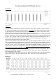
Rear View:
Fredenstein Bento 10S Manual V1.0 Nov 18, 2016 Page 2