
Installation Guide


4
1/4" (6,35 mm)
1/4" (6,35 mm)
1/4" (6,35 mm)
1/4" (6,35 mm)
1/4" (6,35 mm)
1/4" (6,35 mm)
1/4" (6,35 mm)
1/4" (6,35 mm)
1/4" (6,35 mm)
1/4" (6,35 mm)
1/4" (6,35 mm)
1/4" (6,35 mm)
1/4" (6,35 mm)
1/4" (6,35 mm)
1/4" (6,35 mm)
1/4" (6,35 mm)
1/4" (6,35 mm)
1/4" (6,35 mm)
1/4" (6,35 mm)
1/4" (6,35 mm)
1/4" (6,35 mm)
1/4" (6,35 mm)
1/4" (6,35 mm)
1/4" (6,35 mm)
1/4" (6,35 mm)
1/4" (6,35 mm)
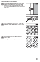
INSTALLING WITH CAP & DIVIDER MOULDINGS:
Pre-drill oversized holes through lattice and moulding
(drill the largest hole that screw head will allow without
tting though) (Fig. 1). Center each screw in oversized
holes and do not overtighten to allow for expansion and
contraction of lattice (Fig. 2).
Along the top, drill and fasten every 24". Drill holes and
hang through both moulding and panel (Fig. 3).
Along the sides and bottom, drill holes and put screws
through moulding only (Fig. 4).
Allow a
1
⁄
1
⁄
1
4
⁄4⁄
" gap on all sides for expansion with cap and
divider mouldings (Fig. 5).
1
2
3
4
Fig. 1
Fig. 2
Wood
Lattice
Molding
Molding
Molding
Molding
1/4" (6,35 mm)
1/4" (6,35 mm)
1/4" (6,35 mm)
1/4" (6,35 mm)
1/4" (6,35 mm)
1/4" (6,35 mm)
1/4" (6,35 mm)
1/4" (6,35 mm)
Fig. 3
1/4" (6,35 mm)
1/4" (6,35 mm)
1/4" (6,35 mm)
1/4" (6,35 mm)
1/4" (6,35 mm)
1/4" (6,35 mm)
1/4" (6,35 mm)
1/4" (6,35 mm)
1/4" (6,35 mm)
Fig. 4
Fig. 5