KVM-08P 8 Port Stackable Keyboard Video Mouse Switch USER’S MANUAL
freedom9 Inc. - 1 Year Limited Warranty Subject to the terms and conditions set forth herein, freedom9 Inc. ("freedom9") provides this limited warranty ("Limited Warranty"): only to the person or entity that originally purchased ("Customer") the product ("Product") from freedom9 or its authorized reseller or distributor.
Table of Contents Chapter 1 Introduction . . . . . . . . . . . . . . . . . . . . . . . .1 Before you start . . . . . . . . . . . . . . . . . . . . . . . . . . . . . . . .1 Features . . . . . . . . . . . . . . . . . . . . . . . . . . . . . . . . . . . . . .2 Specifications . . . . . . . . . . . . . . . . . . . . . . . . . . . . . . . . . .3 Chapter 2 Installation . . . . . . . . . . . . . . . . . . . . . . . . .4 Product details . . . . . . . . . . . . . . . . . . . . . . . . . . . . . . . . .
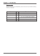
Chapter 1: Introduction Before you start Before you start to install your KVM SWITCH, please make sure that you received the following materials as listed below: Item KVM SWITCH Qty Remark 1 pc. 8 Port Stackable KVM Switch Power Adapter 1 pc. 12V / 1A DC output adapter K/V/M 3 to 3 cable 3 pcs 1 pc : 3 ft, 3 to 3 KVM Cable for daisy chain 2 pcs : 6 ft, 3 to 3 KVM Cable for computer User’s Manual 1 pc. This user’s manual Rack mount bracket 2 pcs. For standard 19” Rack mounting Screw 8 pcs.
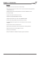
Chapter 1: Introduction Features • 8 computers share one console with On Screen Display • Daisy Chain Port allows you to access a max.
Chapter 1: Introduction Specifications General ■ Size 19” Rack Mount ■ KVM Ports 8 ■ KVM Console Port 1 ■ KVM / Console Port Connector (All Female Type) PS/2 Keyboard (Mini Din 6 pin) PS/2 Mouse (Mini Din 6 pin) VGA HDDB 15 pin ■ Computer selection 1. Hot Key 2. Button 3.
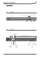
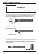
Chapter 2: Installation Product Details 2.1.1 Front View Current Active Bank Display Current Active Port Display 8-Port KVM Switch Bank Select 2.1.
Chapter 2: Installation Push button function Port Status Port Select Bank Select Bank No. Port No. Port Select Reset Bank Select Power On/Off Bank Status Pressing the button cyclically through all the ports. 1 2 3 4 5 6 7 8 Instruction: You can press the button in order as shown in the diagram above. If you switch to a port without computer connection or connected computer is powered-off, the “Port No.” LED will flash. If you switch to a valid computer connection, the “Port No.
Chapter 2: Hardware Installation Rack Installation The KVM switch has a 19” rack mount form factor and can be mounted on any standard 19” rack. Before mounting your KVM switch on a rack, please follow the steps below: Step1. Find a convenient place to put your KVM switch. Step2. Using the attached rack mount brackets, screw it on the 19” rack.
Chapter 2: Hardware Installation Connecting Computers WARNING! Before attempting to connect anything to the KVM switch or the computers, make sure the KVM switch is powered off. Otherwise, plugging and unplugging cables may cause irreversible damage to your computers and the KVM SWITCH. Step 1 Connecting VGA of Console The Console connections will be made with the monitor (VGA) connections first.
Chapter 2: Hardware Installation Step 4 Connecting Keyboard and Mouse Connect the first computer’s mouse/keyboard cable to the KVM SWITCH. If using a PS/2 cable, connect one end to the PS/2 mouse/keyboard port on the computer, and the other end to the “Computer 1” PS/2 mouse/keyboard port on the rear of KVM SWITCH. Make sure both mouse and keyboard have been connected to their appropriate ports. Most cables are color coded to match the connectors. It is a good idea to check this when connecting the cable.
Chapter 2: Hardware Installation Daisy Chain Your Switch If you have more than one Switch you may wish to Daisy Chain them together to allow them to be controlled like one larger switch Step 1. Please use the 3 ft (91.44cm), 3 to 3 KVM cable to daisy chain the KVM, first. Step 2. Use one end of 3 to 3 cable to connect the daisy chain port of bank 1 and the other end for the console port (white color block) of bank 2 KVM switch. Step 3. Repeat step 2 to daisy chain as many banks as you want.
Chapter 3: Console Operation Password Protection There is an administration password for locking the console display and switching between managed computers. This password can be set by using the OSD. The password supports up to 8 digits, and only accepts “ A~Z ” , “ 0~9 ” . The default password is “ 00000000 ” . For security reasons, please change the default password the first time you configure the KVM switch. It is strongly recommend to write down the new password.
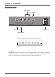
Chapter 3: Console Operation Selecting Computer Using Push Button Current Active Bank Display Bank Select Port Status Bank No. Port No. Port Select Reset Bank Select Port Select Reset Button: Press Port Select and Bank Select of bank 1 (master) simultaneously to reset KVM switch. This reset action will not only return KVM switch back to initial state but it will also re-check any slave banks which are connected to the master KVM switch.
Chapter 3: Console Operation Selecting Computer Using Hot Key You can conveniently command your KVM SWITCH by keyboard hot key entry. To send commands to the KVM SWITCH, the “SCROLL LOCK” key must be pressed twice within 2 seconds, then you will hear a confirmation beep that the keyboard is in hot key mode. If you have not pressed any additional key in hot key mode within 2 seconds, the keyboard will return back to the normal Operation System control state.
Chapter 3: Console Operation Selecting Computer through Hot Key - Example A. To access a computer attached to Port 2 of the third Bank, press hot key combination: within 2 seconds Scroll Scroll Lock Lock 3 0 2 B. To access a computer attached from Bank1 to Bank2, press hot key combination: within 2 seconds Scroll Scroll Page Lock Lock Down NOTE: 1. Bank no. and Port no. selection must be made using the numeric keys on the keyboard.
Chapter 3: Console Operation OSD OPERATION Details When you access the OSD menu by using the hot keys, you will see the following small window pop up on your monitor. The 1st line bar is Bank No. The 2nd block is your KVM’s computer system name list. You will find the system number list from 01 to 08. You can define your system name with a maximum of 8 levels. The factory default of the 8 port KVM switch is “SYSTEM 01”, “SYSTEM 02”,…, “SYSTEM 08”. Sun symbol “ The sun symbol “ status.
Chapter 3: Console Operation OSD OPERATION Details continued 1. The “OSD: 10 SEC” means that the OSD windows display or computer system name will display for 10 sec. on your monitor. You can modify it from 05 sec to 99 sec. The factory default value is 10 sec. 2. “SCAN ” is the scan interval between one KVM port hopped to the next KVM port. The default SCAN time is 10 sec and the maximum scan time is 99 sec. 3.
Chapter 4: Troubleshooting General Problems Q: The OSD menu does not display a “ ” on a channel where a computer is connected and powered up. What do I do? Your KVM SWITCH will update “ ” every 2 seconds. Using the hot keys to access the OSD menu again should have re-detected all the active channels. Q: When cascading the MASTER unit does not see the slave unit(s). One of the following may be the case: • Refer to the Installation section for information on how to properly connect the daisy-chain cable.
Chapter 4: Troubleshooting PS/2 Mouse Problems Q: The mouse is not detected during boot-up. One of the following may be the case: • Check the cables and make sure they are inserted properly in the correct ports. • Check your computer / motherboard documentation making sure that the PS/2 mouse port (or IRQ) is enabled. • Make sure the mouse works when directly plugged into the computer. Rebooting is necessary when trying this.
Chapter 4: Troubleshooting Problem with power switch and power adapter Q: The power switch is off, but the switch still works fine or power adapter is unplugged from the switch, but the switch still works fine? KVM SWITCH draws the power source from power adapter and computer’s PS2 port. Some computer’s PS2 port can support enough power for the switch, but some computer’s PS2 port ( like laptop, notebook computer…etc.) is unable to supply enough power for the switch.
Chapter 5: Certifications FCC This equipment has been tested and found to comply with Part 15 of the FCC Rules. Operation is subject to the following two conditions: (1) This device may not cause harmful interference (2) This device must accept any interference received. Including interference that may cause undesired operation.
© 2005 freedom9 Inc.