USER MANUAL REVISION B | 08.01.
REVISION HISTORY REVISION DATE DESCRIPTION A July 2015 Initial Release B August 2015 Revised section order. Added Allowable Gross Weight table.
CONTENTS 2 Revision History 3 Contents 5 6 ALTA OVERVIEW Disclaimer and Warning 7 LIMITATION OF LIABILITY 8 Introduction 9 Symbols, Abbreviations and Terminology 12 Dimensions 14 Included Items 15 Specifications 19 Limitations 20 System Diagrams 24 ALTA Mobile App 24 Additional Required Components (not included) 25 SETTING UP ALTA 26 Unfolding ALTA 30 Radio Installation 35 Radio Mapping 40 Configuring Top or Bottom Mount 42 Isolator Cartridges 43 Battery Installa
67 Arm Enable Switch 68 Status Light 70 Orientation Lights 71 ALTA App Monitor 72 Data Logging 73 NORMAL PROCEDURES 74 Unpacking and Setup 75 Before Starting 77 Before Takeoff 79 After Every Flight 80 After Last Flight 81 EMERGENCY ROCEDURES 82 Emergency Guidance 83 Pilot Disorientation 84 Unexpected Flight Controller Behavior 85 Battery Exhaustion 86 Status Light Warning Indicator Illuminates 87 Loss of Radio Control Signal 88 Loss of FPV Signal 89 PERFORMANC
ALTA OVERVIEW | USER MANU A L 5
DISCLAIMER AND WARNING IMPORTANT - Please read this disclaimer and warning carefully and review the ALTA User Manual prior to flight. If you have any questions, please contact support@freeflysystems.com prior to using the ALTA. You can review the most current version of this User Manual at www.freeflysystems.com/software-manuals/. By using the ALTA, you acknowledge that you have read, understand and agree to this disclaimer.
LIMITATION OF LIABILITY IN NO EVENT SHALL FREEFLY BE LIABLE TO BUYER FOR ANY INDIRECT, CONSEQUENTIAL, PUNITIVE, INCIDENTAL, OR SPECIAL DAMAGES, OR ANY DAMAGES WHATSOEVER RESULTING FROM THE USE OF THE ALTA OR FROM LOSS OF USE, DATA OR PROFITS (HOWEVER CAUSED AND UNDER ANY THEORY OF LIABILITY), EVEN IF FREEFLY HAS BEEN ADVISED OF THE POSSIBILITY OF SUCH DAMAGES.
INTRODUCTION ALTA is a professional multi-rotor aircraft designed for demanding cinematic, television, and photographic applications. Within five minutes, ALTA can unfold from its carrying case to flying some of the most capable cinema cameras on either the top or bottom of the aircraft. The SYNAPSE flight controller is purpose-built for cinema use, yielding precise, yet smooth control.
SYMBOLS, ABBREVIATIONS AND TERMINOLOGY WARNINGS, CAUTIONS AND NOTES Throughout the manual, warnings, cautions and notes are used to highlight various important procedures. These are defined as follows: WARNING CAUTION Warnings are used to highlight procedures which, if not strictly observed, may result in personal injury or loss of life. Cautions are used to highlight procedures which, if not strictly observed, may cause damage to equipment.
Pressure Altitude Altitude measured from standard sea level pressure (29.92 in. Hhg) by a pressure or barometric altimeter It is the indicated pressure altitude corrected for position and instrument error.
Basic Empty Weight Standard empty weight plus optional equipment Useful Load Difference between take off weight and basic empty weight Payload Useful load less battery weight GENERAL TERMINOLOGY sUAS Small Unmanned Aircraft System includes all components of the system required for the flight of an unmanned aircraft, including the radio controller, data link and other related support equipment | USER MANU A L 11
1 DIMENSIONS 1533 (60.4) 5 2 1064 (41.9) 4 6 457 (18.0) 3 1 1533 (60.4) 5 2 1064 (41.9) 4 6 1126 (44.3) 178 (7.0) 457 (18.0) 3 1 U NFO LD E D P L A N V I E W W I TH B OOM N UM B E RI N G SCHE M E MM (INCH) 5 2 178 (7.0) 318 (12.5) 4 1126 1803 (44.3) (7.1) 457 (18.0) U N FO L D E D S I D E V I E W W I T H L A N D I N G G E A R M M ( I N C H ) 178 (7.0) 318 (12.5) 1126 (44.3) 180 (7.
220 (8.7) FO L D E D S I D E V I E W M M ( I N C H ) 550 550 (21.7) (21.7) FO L D E D P L A N V I E W M M ( I N C H ) 515 515 (20.3) (20.3) 180 180 (7.1) (7.1) 205 205 (8.1) (8.
INCLUDED ITEMS 1. Case 10. Fasteners 2. ALTA 3. Case Lid Foam 4. Isolator Cartridges a. (6) Teal (Installed) b. (6) Black c. (6) Red 5. Documentation 6. USB-Futaba Power Cable 7. Inverted Landing Gear a. (4) M3 × 8 Socket Head for Toad In The Hole Male Adapter b. (2) M3 × 8 Flat Head for Accessory Mount 11. Toad In The Hole Male Adapter 12. 5.5mm Wrench 13. Hex Drivers (1.5mm, 2.0mm, 2.5mm) 14. Accessory Mount 15. Double-Sided Tape 8. Antenna Tubes 9. FP V Cables a. Skyzone/BOSCAM b.
SPECIFICATIONS DIMENSIONS Unfolded Diameter (does not include Props) 1126 mm Folded Diameter (does not include Props) 550 mm Height to base of Toad In The Hole (TITH) 220 mm POWERPLANT Number of Motors Motor Type Motor Model 6 Direct Drive 3-Phase PMAC Outrunner F45 Motor Max Continuous Power Output 350 W Motor Max Instantaneous Peak Power Output 950 W Maximum RPM (flat rated) Equivalent Kv Electronic Speed Controller 6300 RPM 384 Freefly Silent-Drive Sine Wave ESC PROPELLERS Material Propelle
WEIGHTS Maximum Gross for Takeoff1 Maximum Useful Load Maximum Payload 2 13.6 kg (30.0 lbs) 9.1 kg (20.0 lbs) 6.8 kg (15.0 lbs) 3 Typical Standard Empty Weight: 4.5 kg (10.0 lbs) SPECIFIC LOADINGS Typical Specific Power4 Thrust Ratio at MTOW 1 1 At sea level, ISA. 2 Top and bottom mount. Includes batteries. 145 W/kg 1.85 : 1 Payload weight top or bottom mount. Battery weight not included and mounted on opposite side from payload. 3 4 At MTOW, sea level, ISA.
FLIGHT CONTROLLER Model Name Freefly SYNAPSE flight controller Flight Modes Manual, Height Mode, Position Mode, Return-To-Home, Autoland Supported Inputs: DSMX, DSM2, S.Bus, S.Bus2, PPM, FPV SD Supported Radios Futaba S.Bus & S.
PAYLOAD MOUNTING Mounting Locations Mounting System FPV Camera Mount FPV Transmitter Mount | USER MANU A L Bottom and Top Mount Freefly Toad In The Hole (TITH) Quick Release Forward, underneath chassis Boom #5 18
LIMITATIONS NOTE These limitations are advisory in nature and do not extend or restrict limitations provided by local aircraft operational regulation. POWERPLANT LIMITATIONS Maximum RPM 6300 RPM Maximum Battery Voltage 25.2 Volts Minimum Average Battery Voltage 19.2 Volts ENVIRONMENTAL LIMITATIONS Do not fly ALTA in temperatures exceeding 45ºC (113ºF) or below -20ºC(-4ºF).5 WEIGHT LIMITS Maximum Takeoff Weight Maximum Payload 13.6 kg (30.0 lbs) 6.8 kg (15.
SYSTEM DIAGRAMS sUAS OVERVIEW GPS Satellite HD Video Link, Preview Monitor* ALTA App FPV Rx, Preview Monitor* Radio Controller* *NOT INCLUDED 2.
FLIGHT CONTROL SC ESC A. Spektrum Receiver DSMX, DSM 2 B. Futaba Receiver or Generic Receiver S.BUS, S.BUS 2 or PPM SYNAPSE Flight Controller PWM ESC CAN A. B.
POWER SYSTEM Motor Lights* Motor Lights* tb VC A Fu M SYNAPSE Flight Controller FP e aT RE l.
FPV EQUIPMENT F P V Camera (not included) F PV Camera Cable FPV Tx (not included) FPV Camera Lead Pre-installed SYNAPSE Flight Controller FPV Tx Lead Pre-installed FPV Tx Cable Boscam/Skyzone or Fat Shark/ImmersionRC | USER MANU A L 23
ALTA MOBILE APP The ALTA App is used to configure ALTA parameters and to monitor ALTA’s status during flight. To download the ALTA App, search for “Freefly ALTA” in the App Store or on Google Play™. Parameters may only be adjusted while ALTA is on the ground and disarmed. In addition, radio mapping parameters can only be adjusted when the Configuration Jumper is removed. For more information on radio mapping, see the Radio Mapping section of this manual.
SETTING UP ALTA | USER MANU A L 25
UNFOLDING ALTA ALTA features swan-neck booms that fold into a compact size for travel. They are secured in an open position for flight using overcenter latches. TO UNFOLD ALTA 1. Remove ALTA from case 2. Fold down all six boom retention clips 3.
4. Snap shut all six boom latches until they “click” 5. Visually confirm all latches are seated properly 6.
TO FOLD ALTA 1. Secure props with prop protectors 2. Unlatch all six booms 3.
4.
RADIO INSTALLATION RADIO CONTROLLER RECEIVER ALTA requires the installation of a radio control system. S.Bus, S.Bus2, DSM2, DSMX, and PPM (including inverted PPM and Graupner) receiver types are supported. Additionally, ALTA supports radio receiver diversity using S.Bus, S.Bus2, DSM2 and DSMX receivers. This means two receivers may be installed, and the SYNAPSE flight controller will automatically use the receiver with the best signal quality.
3. Identify required wire S.BUS/S.BUS2 PPM DSM2/DSMX 4. Feed wire through grommet 5. Replace side closeout panel 6.
7. Attach receiver/satellite to exterior using the provided double sided tape a. Futaba & PPM b. Spektrum/JR 8. For Futaba receivers, feed antenna wires into antenna tubes and zip tie to noted mounting location 9.
RECOMMENDED RECEIVER PLACEMENT FUTABA Mount Futaba receivers 15mm from the wiring grommet for easy S.Bus wire installation and removal (See Radio Controller Receiver step 7a). SPEKTRUM/JR SATELLITES Mount satellites so antennae are blocked by the airframe as little as possible. If using two receivers, place them at a 90° angle to each other.
3. Feed the voltage sense wires through the grommet on the closeout panel. 4. Connect the white connector to the external voltage sense port on the Futaba receiver.
RADIO MAPPING ALTA can be used with a variety of radio controllers. Different radio controllers can map functions to different channels, so properly mapping controller channels to ALTA functions is an important step before flying. Radio mapping is performed using the ALTA App. This section describes the steps required to complete radio mapping. If you are uncertain about your channel mapping, obtain assistance from an experienced pilot or from Freefly Customer Support.
3. Remove or replace the jumper 4. Reattach the closeout panel MAPPING RADIO CHANNELS USING ALTA APP Channel mapping is accomplished with the ALTA App. Prior to mapping channels, ensure your radio controller and receivers are properly installed. Refer to the Radio Installation section of this manual and your Radio Controller’s documentation. 1.
ONCE CHANNELS ARE MAPPED 7. Remove the battery or USB-Futaba cable from ALTA 8. Replace the Configuration Jumper FUNCTION DESCRIPTIONS The following functions can be mapped to radio controller channels. These are found in the Radio section of the Configurations menu in the ALTA App. Each function is also represented by a chart that responds to control input allowing for quick verification of mapping settings. CONTROLLER Use this to select the appropriate receiver.
available in Height Mode and Position Mode. The clamps can be adjusted mid-flight. An analog dial or slider is recommended for the Velocity and Climb Rate Clamp Functions. ARM ENABLE Arm Enable is an optional safety feature that inhibits arming while on the ground, or disarming while in the air based on the position of the switch. When not mapped, ALTA may be armed or disarmed at any time following normal arming and disarming procedures.
Climb Rate Clamp Arm Enable Switch Top Fast Bottom Slow Top Arm Enable / Disarm Disable Middle Arm Enable / Disarm Enable Bottom Arm Disable / Disarm Enable TYPICAL CHANNEL MAPPINGS The following are channel mapping configurations as set in the ALTA App. These are recommendations only. Depending on exact radio models, these may help as an initial configuration. However, it is up to the pilot setting up ALTA for flight to determine if these settings are appropriate.
CONFIGURING TOP OR BOTTOM MOUNT A MōVI can be attached to either the top or bottom of ALTA via the Freefly Toad In The Hole (TITH) quick release. ALTA comes pre-configured for bottom mounting a MōVI. BOTTOM MOUNT 1. 2. Prepare your MōVI for bottom-mount flight (see MōVI manual) a. Attach landing gear b. Install TITH receiver on MōVI Connect MōVI to bottom Toad ADDING A TITH TOP MOUNT CAUTION Top mounting is not supported by the MōVI M10. 1. Prepare your MōVI for top-mount flight a.
2. Connect and secure the supplied inverted landing gear to the bottom Toad 3. Remove the four flat-head M3×6 bolts that secure the top handle 4. Attach the supplied Toad to the top plate using the four M3×8 bolts provided 5.
ISOLATOR CARTRIDGES Different Isolator Cartridges can be used to fine tune vibration damping performance for different payload weights. Three isolation cartridge styles are provided with ALTA with the red for light payloads, teal for medium payloads, and black for heavy payloads. Flight testing may be required to determine the optimal isolator for a given setup. To install, place the cartridges between the top chassis plate and the battery plate.
BATTERY INSTALLATION Batteries may be installed on either the top or bottom of an ALTA and are always mounted opposite of the payload location. In both locations, battery pack(s) are secured with silicone straps tensioned across the pack(s). The straps are secured using studs located on either side of the pack(s). WARNING Always secure battery pack(s) with both battery retention straps.
BOTTOM MOUNT 1. Place battery retention strap studs at the appropriate height for battery pack(s) 2. Adjust battery stops to fit battery pack(s) 3.
4. Place battery pack(s) on battery tray below handle 5.
TOP MOUNT CAUTION Always completely secure the inverted landing gear by closing the TITH quick release lever. Inverted landing gear that are not completely attached can rotate and unplug battery leads. 1. Adjust battery stops to fit battery pack(s) 2. Attach the single-hole end of the battery retention strap to a stud on the landing gear 3. Place battery packs(s) in landing gear 4.
COMPASS CALIBRATION For best results, it is recommended to perform manual compass calibrations away from ferrous objects, buildings and vehicles. In addition, concrete can contain steel rebar which may influence compass calibrations. WARNING Verify ALTA is disarmed prior to performing a compass calibration. To ensure ALTA does not arm, set the Arm Enable Switch (if available) to disable, and remove the Configuration Jumper.
AUTOMATIC COMPASS CALIBRATION Automatic Compass Calibration will use compass readings over time to resolve an accurate compass calibration. Manual calibration is recommended when moving to a new location and an accurate compass calibration is needed immediately for using position mode. In the ALTA App, select Configurations > More > Compass. Change the Auto Calibration setting to On.
PROPELLERS The folding propellers include two carbon fiber propeller blades attached to prop hubs, which are themselves secured to the motors. The propellers installed on booms 1, 3 and 5 spin clockwise when viewed from above ALTA, and the propellers installed on booms 2, 4 and 6 spin counterclockwise when viewed from above. For information on propeller installation and maintenance, refer to the Maintenance section of this manual.
CHECKING PROP BOLT TIGHTNESS Over time, the bolts that hold the propeller blades to the prop hub can loosen due to vibration. To check prop bolt tightness, twist the prop about its length. If there is free play, the prop bolt is too loose. Use the provided 2.5mm hex driver and wrench to tighten the bolt and nut that secure the prop blade just enough to remove the play. CAUTION Do not overtighten, or the prop may fail to unfold completely during motor start up, leading to excessive vibration.
FIRST PERSON VIEW (FPV) ALTA and SYNAPSE can power a variety of first person view (FPV) cameras and transmitters, as well as add informational on-screen display (OSD) elements to aid in FPV flying. Two FPV transmitter cables are included. The cable with two connectors on one of the ends will run ImmersionRC and Fat Shark systems, and the cable with a single connector on the end will run Boscam and SkyZone systems. A single camera cable is provided, and is configured to run a Ready Made RC camera.
2. Locate the FPV camera cable included in the ALTA package. 3. Remove the front closeout panel with a 1.5 mm hex driver. 4. Pass the FPV cable through the grommet, and connect to the mating FPV camera lead inside ALTA. Connect the other end directly to the camera. 5. Replace front closeout panel.
TRANSMITTER 1. Mount FPV transmitter on the provided carbon fiber accessory mount plate. 2. Attach Accessory Mount to boom 5 with M3×8 flathead bolts. 3. Locate the appropriate FPV transmitter cable. The following cables are included: 4. a. ImmersionRC/Fat Shark (cable with two connectors) b. Boscam/SkyZone (cable with one connector) Remove the side closeout panel with the FPV transmitter lead using the 1.5mm hex driver.
5. Pass transmitter cable through the underside of the hinge, and connect to the FPV transmitter lead. 6. Replace side closeout panel. 7. Zip tie the FPV transmitter lead to the boom cable bundle for strain relief. FPV ON SCREEN DISPLAY SETUP A number of properties and components can be adjusted or added to the FPV On Screen Display (OSD) using the ALTA App.
TEXT COMPONENTS The following components are displayed as text items, and can be configured to display as big or small letters, or no letters effectively turning off the display.
Basic Adds small dash marks on the left and right side of the artificial horizon that indicate changes in roll Horizon Adds marks to include a full horizon line Ladder Adds small marks on either side of the artificial horizon ladder that roll with ALTA roll movements Pitch and Roll Scaling 10, 20, 30, 40 Allows for scaling of the artificial horizon markings to compensate for FPV cameras of different field views Pitch and Intervals 10, 20, 30, 40 Sets the number of degrees between pitch markings w
TUNING ALTA | USER MANU A L 57
TUNING ALTA ALTA comes pre-tuned for a wide variety of payloads and flying conditions. Generally, additional tuning is not required to fly ALTA, and additional tuning will only need to take place if more customization of control feel is desired. Default tuning values are included in Appendix A, Default Tuning Values. Parameters fall into three categories - Attitude, Height and Position.
tuning. When tuning Stiffness first, or making large stiffness changes, Hold Strength should be set to a low, non-zero value. Higher Stiffness values give more responsive control. Values that are too high can cause instability or oscillation. WARNING Excessively high stiffness values can cause ALTA to become unstable and difficult or even impossible to control. Lower Stiffness values give less responsive control. Values that are too low can cause a vague or disconnected control response.
Decrease this value if ALTA experiences vertical oscillation or vibration. Increase this value if ALTA is sluggish while accelerating to a desired climb or descent rate in Height mode. HOLD STRENGTH Hold Strength Gain tunes how much ALTA will attempt to stay on a desired altitude in Height Hold mode only. A higher value will result in height being held more precisely. Too high of a value can cause ALTA to overreact to winds, gusts or turbulent air.
ALTA FLIGHT PARAMETERS Flight Parameters are different from tuning parameters in that the flight characteristics of ALTA will not change with their modification. However, they can be used to select neutral points using trim, or to set maximum or minimum values. ATTITUDE PITCH AND ROLL TRIM Use Pitch and Roll trim settings to correct for tendencies of the ALTA to pitch or roll with a neutral control input.
below center stick. Alternatively, if ALTA climbs when switching from Manual to Height mode, increase hover throttle, since a climb indicates a stick position that is higher than neutral in Manual mode. If ALTA descends, decrease hover throttle, since a descent indicates a stick position that is lower than neutral in Manual mode. NOTE The ALTA App does not allow hover throttle adjustments while ALTA is flying.
follow the lower of these two limits. MAXIMUM GPS SPEED Max GPS Speed sets the maximum speed ALTA will fly across the ground at full stick deflection in Position Mode. If Velocity Clamp is mapped to an RC transmitter channel, the parameter will adjust the fastest ground speed available to the Velocity Clamp feature. RANGE Range sets the maximum distance ALTA may fly away from the home point while in Position mode. If the range is exceeded in Manual mode, the status light will illuminate white.
OPERATING ALTA | USER MANU A L 64
FLIGHT CONTROLLER MODES ALTA has three primary flight control modes: Manual Mode, Height Mode, and Position Mode. They are selected with the Mode Switch CAUTION Always neutralize control inputs when switching between control modes. MANUAL MODE In Manual Mode, ALTA will only stabilize its attitude. At neutral control input (middle pitch and roll stick position), ALTA will attempt to remain level. Throttle control is direct.
CAUTION Flight using Position Mode in areas of degraded GPS signal, such as near buildings or under dense tree cover, is not recommended. The automatic reversion to Manual Mode can cause unexpected, abrupt changes in flight behavior. RETURN-TO-HOME Return-To-Home Mode will command ALTA to fly back to the starting point of the flight or the last defined Home Point. When ALTA first acquires a GPS position, it sets this as the Home Point of the flight.
AUTOLAND The Autoland function will command ALTA to hover for 10 seconds and will then land in place. This only occurs if Autoland is selected as the Loss of Signal (LOS) event in the ALTA App, or at the end of an LOS Return-to-Home (RTH) event. If ALTA is above the app-configurable Safe Height setting, ALTA will first descend to the Safe Height at the Maximum Descent Rate. After reaching this height, ALTA’s descent will slow to the Autoland Descent Rate until landing.
STATUS LIGHT The rear-facing Status Light shows the status of ALTA as it boots, arms and flies. The following table shows the different meanings of the light in the various flight phases.
Flight - Manual Mode Flight - Height Hold Flight - Position Hold Off Nominal flight status No errors Solid White Outside user-defined range, height or speed limits Off Nominal flight status Height hold inactive Slow Flashing White Height hold active Flashing Red Battery cell voltage below user-defined levels Off Nominal flight status Height hold inactive Position hold inactive Slow Flashing White Height Hold or Position Hold Active Fast Flashing White Height Hold and Position Hold Active Fl
ORIENTATION LIGHTS BOTTOM VIEW The boom-end mounted Orientation Lights indicate both the orientation of ALTA in flight and the status of the individual motor Electronic Speed Controllers (ESCs) during other flight phases. The following table shows the different meanings of the light colors in the various flight phases.
ALTA APP MONITOR The ALTA App includes a flight status monitor that displays information about the health of the ALTA and the various controls that can be selected. Boot indicates if the SYNAPSE booting process has completed successfully. Any issues that prevented a normal boot are indicated here. Battery displays the voltage of the battery pack. Status displays the state of the SYNAPSE flight controller. Radio displays if the SYNAPSE detects a radio controller signal.
DATA LOGGING ALTA automatically logs flight and control data when ALTA is armed for flight. Data is recorded as a .csv file at a rate of 25 Hz on a microSD card installed on the top of the GPS/Compass module. A table of recorded data is included in Appendix B.
NORMAL PROCEDURES | USER MANU A L 73
UNPACKING AND SETUP 1. Aircraft 2. Prop protectors 3. Boom retention clips 4. Booms 5. Boom latches 6. Receivers and wiring 7. Isolator cartridges 8. Payload mounting location REMOVE from case REMOVE STOW UNFOLD LOCK CHECK SELECT and INSTALL as necessary CONFIGURE as necessary AMPLIFICATION To set up ALTA for flight, remove it from the case and remove the prop protectors. Stow the six boom retention clips by folding them down.
BEFORE STARTING 1. Payload 2. Isolator Cartridges SECURED 3. microSD Card 4. Props 5. Prop Hub 6. Motors 7. Radio Controller 8. Radio Controller Model 9. Aircraft Placement 10. Battery Pack Voltage 11. Battery Packs SECURE 12. Battery Leads CHECK CONDITION and CONNECT 13. Aircraft 14. Flight Controller 15. Status Light 16. Orientation Lights 17. Receivers VERIFY BOUND 18. ALTA App CONNECT 19. ALTA App Monitor 20. Compass Calibration AS REQUIRED 21.
Motors should spin freely, and there should be no grinding or scraping sound from the motor. The inside of the motor should be free of debris. Always turn on the radio controller before plugging in ALTA. Follow the battery installation guidance in the Battery Installation section of this manual for battery installation instructions. While the SYNAPSE flight controller initializes, keep the ALTA as stable as possible.
BEFORE TAKEOFF 1. Prop Area 2. Mode Switch MANUAL CLEAR 3. Home Switch CENTER POSITION 4. Radio Controller 5. Telemetry (if equipped) 6. Arm Enable Switch 7. ALTA 8. Status Light 9. Orientation Lights VERIFY USER-DEFINED COLOR 10. Motors START and VERIFY OPERATION 11. Flight Controls 12.
motors are spinning. Keep the throttle in the lowest position and move the pitch, roll and yaw controls slightly. ALTA should pitch, roll and yaw slightly due to isolator cartridge flex. Ensure that the ALTA behaves as expected. If it does not, shutdown ALTA and ensure the props are installed in the correct orientation. CAUTION Do not make large yaw commands while on the ground with the inverted landing gear installed. Large yaw commands can cause instability.
AFTER EVERY FLIGHT 1. Mode Switch MANUAL 2. Home Switch CENTER POSITION 3. Arm Enable Switch 4. ESCs and Motors 5. Arm Enable Switch 6. Orientation Lights 7. Status LED 8. ALTA App CHECK for warnings 9. Batteries DISCONNECT and REMOVE 10. Radio Controller Power 11. Aircraft Condition INSPECT 12. Motor and Prop Condition INSPECT 13.
AFTER LAST FLIGHT 1. Props 2. Prop Protectors FOLD and PLACE inline with booms INSTALL 3. Boom Latches UNLOCK 4. Booms 5. Boom Retention Clips EXTEND 6. Payload REMOVE 7. ALTA FOLD INSERT into case AMPLIFICATION Packing ALTA is similar to the unpacking process. Keeping ALTA on the payload or landing gear facilitates the process as ALTA may be turned on the Toad In The Hole adapter while folding the props and booms.
EMERGENCY PROCEDURES | USER MANU A L 81
EMERGENCY GUIDANCE The emergency procedures listed in this section are the recommended practices for handling the aircraft in the event of an aircraft emergency. This guidance should be considered and applied as necessary. The risk of an emergency occurring can be reduced substantially through proper aircraft maintenance, by performing thorough inspections before and after all flights, and with careful pre-flight planning.
PILOT DISORIENTATION 1. Control Inputs 2. Mode Switch NEUTRALIZE 3. Yaw NOSE AWAY 4. Roll VERIFY DIRECTION POSITION AMPLIFICATION Regaining spatial orientation as quickly as possible is most important. In disorientation situations, control inputs will not give the expected result, so neutralize them. If a good GPS signal is available, enable Position Mode so ALTA will stay in a one place.
UNEXPECTED FLIGHT CONTROLLER BEHAVIOR 1. Control Inputs 2. Mode Switch NEUTRALIZE MANUAL If the problem persists 3. ALTA LAND as soon as possible AMPLIFICATION If the ALTA behaves unexpectedly, neutralize control inputs and observe ALTA. If it is still flying in an uncommanded manner, switch to Manual mode if it is in Height or Position modes. In most cases, unexpected behavior is due to erroneous sensor readings, or degraded GPS signal reception.
BATTERY EXHAUSTION If battery cell voltage is between Alarm Voltage and Land Voltage 1. Status Light 2. ALTA Illuminates red (solid or blinking) LAND as soon as possible If battery cell voltage is below Land Voltage 1. ALTA 2. Pitch and Roll Begins Autoland MANEUVER away from people or objects AMPLIFICATION If the battery cell voltage drops below the Alarm Voltage, the Status Light will turn solid red in Manual Mode, or turn blinking red if holding position or altitude.
STATUS LIGHT WARNING INDICATOR ILLUMINATES 1. Mode Switch 2. ALTA 3. ALTA App MANUAL LAND as soon as possible OPEN MONITOR AMPLIFICATION The Status Light can turn red, indicating a warning, for a number of different reasons. It is always recommended to land as soon as possible and investigate the problem while ALTA is on the ground.
LOSS OF RADIO CONTROL SIGNAL 1. Controller Battery CHECK 2. Controller Antenna 3. Mode Switch POSITION 4. Home Switch RETURN-TO-HOME REPOSITION AMPLIFICATION Loss of Signal (LOS) can occur if the radio controller stops transmitting a signal, or if ALTA is too far away to receive it. In the event ALTA detects a LOS, it will automatically execute a Return-to-Home or Autoland as configured in the App.
LOSS OF FPV SIGNAL 1. Control Inputs AS REQUIRED 2. Visual Contact ESTABLISH 3. ALTA POSITION for optimal signal reception If visual contact or FPV signal is not reestablished 1. Mode Switch POSITION 2. Home Switch RETURN TO HOME 3. Throttle AS REQUIRED AMPLIFICATION An FPV Loss of Signal (LOS) can occur if the aircraft flies out of range, or if it flies behind an object that interrupts the signal line of sight.
PERFORMANCE | USER MANU A L 89
PERFORMANCE WEIGHT / ENDURANCE PERFORMANCE DATA Conditions: Altitude Winds Sea Level, ISA Zero | USER MANU A L 90
ALLOWABLE GROSS WEIGHT ALLOWABLE GROSS WEIGHT As altitude and temperature increase, the density of the air decreases. Consequently, ALTA’s thrust will decrease. The following table describes maximum gross weight limits with respect to altitude and temperature. 4000 3000 2000 1000 S.L. 26.3 27.3 28.4 29.4 30.0 30.0 Maximum Gross Weight (lb) 11.5 11.9 12.4 12.9 13.3 13.6 13.6 Maximum Gross Weight (kg) 23.5 24.5 25.4 26.4 27.4 28.4 29.4 30.0 Maximum Gross Weight (lb) 10.3 10.
MAINTAINING ALTA | USER MANU A L 92
GENERAL INFORMATION AND TECHNIQUES USE OF THREADLOCKER Bolts and screws that are called out in this manual to regularly remove or replace typically do not require use of a threadlock compound. This includes the screws holding on the handle, battery retention strap studs, battery stops, closeout panels, the top male Toad In The Hole adapter. In addition, fasteners that attach to nuts with a nylon locking feature (nylock nuts) do not require threadlocker.
MAINTENANCE ITEMS PROPELLERS Propeller blades should be removed when making a change to the configuration of the ALTA to prevent propeller strikes in the event of unintentional motor starts and should be replaced on an as needed basis if they become damaged. Generally, a nick on the leading edge that is large enough to catch a fingernail indicates that the prop should be replaced. If the blade composite structure becomes delaminated, the propeller blade should be replaced.
Odd numbered booms (1, 3 and 5) use clockwise rotating props when looking from the top down, and even numbered booms (2, 4 and 6) use counterclockwise rotating props. WARNING Always check to ensure the correct prop rotation direction and correct propeller prior to flight. Props that spin in the incorrect direction will cause ALTA to be uncontrollable. REPLACING PROPELLER BUMPERS Under normal use, propeller bumpers may split and fall out of the folding propeller assembly.
EVERY 15 FLIGHTS ALTA is designed to be as maintenance-free as is possible. It is recommended to check ALTA’s fasteners regularly. This check should occur roughly after every 15 flights, dependent upon the level of vibration ALTA experiences in flight or during handling. To check ALTA’s fasteners, apply a tightening torque to each fastener on the chassis using the supplied hex drivers. The fasteners should not slip.
FIRMWARE UPDATE PROCESS NOTE Carefully follow in-app instructions for saving and restoring ALTA configuration settings during the firmware update process. WARNING Remove propellers before performing a firmware update. Test radio channels, arming and disarming behavior after firmware updates to ensure radio mapping has been preserved. Incorrect radio mapping can lead to loss of control. SYNAPSE firmware is updated using the ALTA App. New app updates may include new firmware installations.
TROUBLESHOOTING | USER MANU A L 98
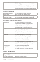
GENERAL WARNINGS SY M P TO M Compass Warning GPS Warning P OTENT I AL CAU SE P OT E NTI AL SO LUTIO N microSD card is missing Check the microSD card is installed Compass calibration is invalid Recalibrate the compass GPS/Compass Unit has become disconnected Check the GPS/Compass unit wiring for damage FLIGHT CONTROLLER SY M P TO M ALTA will not arm P OTENT I AL CAU SE P OT E NTI AL SO LUTIO N ALTA Home Switch not in middle position Move Home Switch to middle position ALTA Mode Switch not in
FLIGHT BEHAVIOR SY M P TO M P OTENT I AL CAU SE P OT E NTI AL SO LUTIO N ALTA does not maintain level pitch or roll Pitch or Roll Trim position not set Use the ALTA app to set the appropriate pitch and roll trim ALTA does not maintain heading ALTA yaw during boot Re-initialize SYNAPSE while keeping ALTA stationary in all directions Compass calibration is invalid Recalibrate the compass Position Hold tuning values too high Reduce Position Hold tuning values, starting with Position Hold Strength
APPENDIX | USER MANU A L 101
APPENDIX A. DEFAULT TUNING VALUES PA RA ME T E R GROUP Attitude Height Position Safety PA RAM E T E R DEFAULT VALUE Pitch/Roll Stiffness 65 Pitch/Roll Hold Strength 50 Yaw Stiffness 100 Yaw Hold Strength 100 Roll Trim 0 Pitch Trim 0 Maximum Pitch/Roll Angle 40° Maximum Yaw Rate 100°/sec Vertical Stiffness 20 Hold Strength 80 Hover Throttle 14.0V Ceiling 118 meters Climb Rate 3 meters/sec GPS Height Correction On Horizontal Stiffness 30 Hold Strength 40 Maximum G 0.
APPENDIX B. DATA LOGGING FIELDS FI E L D U N I TS DESCRI P T I ON Reading Unitless An indexed identifier assigned to data points IMU Time Seconds The number of seconds from arming ALTA GPS Time HH:MM:SS The Universal Coordinated Time determined by received GPS signals.
IMU Position North meters The IMU derived dead-reckoned distance ALTA has traveled northward IMU Position East meters The IMU derived dead-reckoned distance ALTA has traveled eastward IMU Position Up meters The IMU derived dead-reckoned distance ALTA has traveled upward IMU Velocity North meters / second The IMU derived northward velocity component of ALTA. IMU Velocity East meters / second The IMU derived eastward velocity component of ALTA.
IMU Acceleration Z G The IMU derived body acceleration where positive values are in an upwards direction and excludes gravity Compass X Unitless A component of a unit magnetic vector with positive values directed to the front when front is pointing Northward Compass Y Unitless A component of a unit magnetic vector with positive values directed to the right when front is pointing Westward Compass Z Unitless A component of a unit magnetic vector with positive values directed to down when the unders
Roll Rate Command deg/s The roll rate control loop set point where positive values are for rolling rightwards Pitch Rate Command deg/s The pitch rate control loop set point where positive values are for pitching upwards Yaw Rate Command deg/s The yaw rate control loop setpoint where positive values are rotating clockwise looking from the machine top Radio Roll us RC pulse width 1000-2000us where increasing values are for roll right Radio Pitch us RC pulse width 1000-2000us where increasing val
Motor Energy 1-6 Watt-hours Integrated ESC power consumption - can be used to compare motor efficiencies or thrust skew Motor Accel 1-6 a.u.
Attitude Mode register Status indicating angle or rate control mode Position Lock 2 register Status indicating position control mode Height Lock register Status indicating height control mode CRC Failures number Internal communication errors | USER MANU A L 108