AIRCRAFT FLIGHT MANUAL 770-0 0 0 4 2 | R E V I S I O N D | 0 1 . 1 6 .
REVISION HISTORY REVISION DATE DESCRIPTION A July 2015 Initial Release B August 2015 Revised section order. Added Allowable Gross Weight table. C October 2015 Revised for clarity. Added Disarm Safety function and WiFi password reset information. Revised default tuning values to reflect SYNAPSE version 3.4. D January 2017 Added discussion of features available in SYNAPSE version 4.0.4. Added Kinematic Position Mode. Added Orbit Mode. Updated Alarm Light scenarios.
CONTENTS 2 Revision History 3 Table of Contents 6 7 ALTA 6 OVERVIEW Disclaimer and Warning 9 Limitation of Liability 10 Introduction 11 Symbols, Abbreviations, and Terminology 14 Dimensions 16 Included Items 17 Specifications 21 Limitations 23 System Diagrams 27 ALTA Mobile App 28 Additional Required Components (not included) 29 SETTING UP ALTA 6 30 Unfolding/Folding ALTA 6 33 Radio Installation 38 Radio Channel Mapping 44 Configuring for MōVI 46 Isolator Cartridge
80 Orbit Switch 81 Disarm Safety Switch 82 Status Light 84 Orientation Lights 85 Alarms 86 ALTA App Monitor 87 Data Logging 88 NORMAL PROCEDURES 89 Unpacking and Setup 90 Before Starting 92 Before Takeoff 94 After Every Flight 96 After Last Flight 97 EMERGENCY PROCEDURES 98 Emergency Guidance 99 Alarm Indication (Flashing or Solid Red Light) 100 Pilot Loss of ALTA 6 Orientation 101 Unexpected Flight Controller Behavior 102 Battery Exhaustion 103 Radio Loss of Sig
119 TROUBLESHOOTING 124 APPENDIX 125 Appendix A. Default Tuning Values 126 Appendix B.
ALTA 6 OVERVIEW | AIRCRAFT FLIGHT MANUAL 6
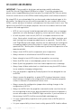
DISCLAIMER AND WARNING IMPORTANT - Please read this disclaimer and warning carefully and review the ALTA 6 Aircraft Flight Manual (AFM) prior to flight. If you have any questions, please contact support@freeflysystems.com prior to using the ALTA 6. You can review the most current version of this AFM at www.freeflysystems.com/software-manuals/. By using ALTA 6, you acknowledge that you have read, understand and agree to this disclaimer.
to all applicable rules and regulations. »» Fly at your own risk. »» ALTA 6 is a tuned system with custom components selected for each application. Modification to, removal, or substitution of ALTA 6 components will void the warranty and can lead to unsafe operating conditions.
LIMITATION OF LIABILITY IN NO EVENT SHALL FREEFLY BE LIABLE TO BUYER FOR ANY INDIRECT, CONSEQUENTIAL, PUNITIVE, INCIDENTAL, OR SPECIAL DAMAGES, OR ANY DAMAGES WHATSOEVER RESULTING FROM THE USE OF ALTA OR FROM LOSS OF USE, DATA OR PROFITS (HOWEVER CAUSED AND UNDER ANY THEORY OF LIABILITY), EVEN IF FREEFLY HAS BEEN ADVISED OF THE POSSIBILITY OF SUCH DAMAGES.
INTRODUCTION ALTA 6 is a professional multi-rotor aircraft designed for demanding cinematic, television, and photographic applications. Within five minutes, ALTA 6 can unfold from its carrying case to flying some of the most capable cinema cameras on either the top or bottom of the aircraft. The SYNAPSE flight controller is purpose-built for cinema use, yielding precise yet smooth control.
SYMBOLS, ABBREVIATIONS, AND TERMINOLOGY WARNINGS, CAUTIONS AND NOTES Throughout the manual, warnings, cautions and notes are used to highlight various important procedures. These are defined as follows: WARNING CAUTION Warnings are used to highlight procedures which, if not strictly observed, may result in personal injury or loss of life. Cautions are used to highlight procedures which, if not strictly observed, may cause damage to equipment.
Pressure Altitude Altitude measured from standard sea level pressure (1013.2 mbar, 29.92 in. Hg) by a pressure or barometric altimeter It is the indicated pressure altitude corrected for position and instrument error.
WEIGHT AND BALANCE Maximum Takeoff Weight (MTOW) Maximum allowable weight at liftoff Standard Empty Weight Weight of a standard aircraft Basic Empty Weight Standard empty weight plus optional equipment Useful Load Difference between take off weight and basic empty weight Payload Useful load less battery weight GENERAL TERMINOLOGY LOS Loss of Signal RTH Return-to-Home sUAS Small Unmanned Aircraft System includes all components of the system required for the flight of an unmanned aircraft, incl
1 DIMENSIONS 1533 (60.4) 5 2 1064 (41.9) 4 6 457 (18.0) 3 1 1533 (60.4) 5 2 1064 (41.9) 4 6 1126 (44.3) 178 (7.0) 457 (18.0) 3 1 U NFO LD E D P L A N V I E W W I TH B OOM N UM B E RI N G SCHE M E MM (INCH) 5 2 178 (7.0) 318 (12.5) 4 1126 1803 (44.3) (7.1) 457 (18.0) U N FO L D E D S I D E V I E W W I T H L A N D I N G G E A R M M ( I N C H ) 178 (7.0) 318 (12.5) 1126 (44.3) 180 (7.
220 (8.7) FO L D E D S I D E V I E W M M ( I N C H ) 550 550 (21.7) (21.7) FO L D E D P L A N V I E W M M ( I N C H ) 515 515 (20.3) (20.3) 180 180 (7.1) (7.1) 205 205 (8.1) (8.
INCLUDED ITEMS 1. Case 10. Fasteners 2. ALTA 6 3. Case Lid Foam 4. Isolator Cartridges a. (6) Teal (Installed) b. (6) Black c. (6) Red 5. Documentation 6. USB-Futaba Power Cable 7. Inverted Landing Gear 8. Antenna Tubes a. (4) M3 × 8 Socket Head for Toad In The Hole Male Adapter b. (2) M3 × 8 Flat Head for Accessory Mount 11. Toad In The Hole Male Adapter 12. 5.5mm Wrench 13. Hex Drivers (1.5mm, 2.0mm, 2.5mm) 14. Accessory Mount 15. Double-Sided Tape 16. Electronic Luggage Scale 9. FP V Cables a.
SPECIFICATIONS DIMENSIONS Unfolded Diameter (does not include Props) 1126 mm Folded Diameter (does not include Props) 550 mm Height to base of Toad In The Hole (TITH) 220 mm POWERPLANT Number of Motors Motor Type Motor Make and Model 6 Direct Drive 3-Phase PMAC Outrunner Freefly F45 Motor Max Continuous Power Output 350 W Motor Max Instantaneous Peak Power Output 950 W Maximum RPM (flat rated) Equivalent Kv Electronic Speed Controller 6300 RPM 384 Freefly Silent-Drive Sine Wave ESC PROPELLERS
WEIGHTS Maximum Gross for Takeoff1 Maximum Useful Load 2 13.6 kg (30.0 lbs) 9.1 kg (20.0 lbs) Maximum Payload3 6.8 kg (15.0 lbs) Typical Standard Empty Weight: 4.5 kg (10.0 lbs) WA R N I N G Always refer to the following aircraft limitations section for complete information on allowable maximum gross weights at different altitudes and temperatures before any flight. SPECIFIC LOADINGS Typical Specific Power4 Thrust Ratio at MTOW 1 145 W/kg 1.85 : 1 At sea level, ISA.
FLIGHT CONTROLLER Model Name Freefly SYNAPSE flight controller Flight Modes Manual, Height Mode, Position Mode (Classic, Kinematic), Return-to-Home (RTH), Autoland, Orbit Mode Supported Inputs: DSMX, DSM2, S.Bus, S.Bus2, PPM, FPV SD Supported Radios Futaba S.Bus & S.
PAYLOAD MOUNTING Mounting Locations Mounting System FPV Camera Mount FPV Transmitter Mount | AIRCRAFT FLIGHT MANUAL Bottom and Top Mount Freefly Toad In The Hole (TITH) Quick Release Forward, underneath chassis Boom 5 20
LIMITATIONS N OT E These limitations are advisory in nature and do not extend or restrict limitations provided by Governing Aviation Authorities. POWERPLANT LIMITATIONS Maximum RPM 6300 RPM Maximum Battery Voltage 25.2 Volts Minimum Average Battery Voltage 19.2 Volts ENVIRONMENTAL LIMITATIONS Do not fly ALTA 6 in temperatures exceeding 45ºC (113ºF) or below -20ºC(-4ºF).
30.0 30.0 29.4 28.4 27.3 26.3 25.4 24.4 23.5 22.6 21.8 305m (1000ft) 610m (2000ft) 914m (3000ft) 1219m (4000ft) 1524m (5000ft) 1829m (6000ft) 2134m (7000ft) 2438m (8000ft) 2743m (9000ft) 3048m (10000ft) Maximum Gross Weight (lb) Sea Level Press Alt Ft | AIRCRAFT FLIGHT MANUAL 9.9 10.3 21.0 21.8 9.5 9.9 10.3 10.7 11.1 11.5 12.0 12.4 12.9 13.4 13.6 Maximum Gross Weight (kg) 20.3 21.1 21.9 22.7 23.6 24.5 25.5 26.4 27.4 28.4 29.5 Maximum Gross Weight (lb) 9.
SYSTEM DIAGRAMS sUAS OVERVIEW GPS Satellite HD Video Link, Preview Monitor* ALTA App FPV Rx, Preview Monitor* Radio Controller* *NOT INCLUDED 2.
FLIGHT CONTROL SC ESC A. Spektrum Receiver DSMX, DSM 2 B. Futaba Receiver or Generic Receiver S.BUS, S.BUS 2 or PPM SYNAPSE Flight Controller PWM ESC CAN A. B.
POWER SYSTEM Motor Lights1 * Motor Lights 6* tb VC A Fu M SYNAPSE Flight Controller FP e aT RE l. IV VT x CE FP ER FUSE Motor Lights 5* Motor Lights 2* FUSE RE CE IV ER 12v 5v 5v Note: Do not modify, augment, or add components to the electrical power system of the ALTA. Unauthorized modifications may result in unsafe operation.
FPV EQUIPMENT F P V Camera (not included) F PV Camera Cable FPV Tx (not included) FPV Camera Lead Pre-installed SYNAPSE Flight Controller FPV Tx Lead Pre-installed FPV Tx Cable Boscam/Skyzone or Fat Shark/ImmersionRC | AIRCRAFT FLIGHT MANUAL 26
ALTA MOBILE APP The ALTA App is used to configure ALTA 6 parameters, update ALTA 6 firmware, and to monitor ALTA 6 status during flight. To download the ALTA App, search for “Freefly ALTA” in the App Store or on Google Play™. Parameters may only be adjusted while ALTA 6 is on the ground and disarmed. In addition, radio mapping parameters can only be adjusted when the Configuration Jumper is removed. For more information on radio mapping, see the Radio Mapping section of this manual.
ADDITIONAL REQUIRED COMPONENTS (NOT INCLUDED) RADIO CONTROLLER ALTA 6 supports a variety of radio controllers as outlined in the Flight Controller Specifications. A minimum of five (5) channels are required, with four (4) used for flight control, and the remaining one (1) used for mode selection. However, a radio controller with at least 10 channels is highly recommended to make use of Velocity and Climb Rate Clamps, Return-to-Home (RTH), Disarm Safety, and Orbit Mode functions.
SETTING UP ALTA 6 | AIRCRAFT FLIGHT MANUAL 29
UNFOLDING ALTA 6 ALTA 6 features swan-neck booms that fold into a compact size for travel. They are secured in an open position for flight using overcenter latches. TO UNFOLD ALTA 6 1. Remove ALTA 6 from case 2. Fold down all six boom retention clips 3. Open ALTA 6 booms. ALTA 6 can become unbalanced and tip over while unfolding booms individually, so unfold opposite boom pairs simultaneously to keep balance.
4. Snap shut all six boom latches until they click and latch 5. Visually confirm all latches are seated properly 6.
TO FOLD ALTA 6 1. Secure props with prop protectors 2. Unlatch all six booms 3. Close ALTA 6 booms in opposing pairs to keep balance 4.
RADIO INSTALLATION RADIO CONTROLLER RECEIVER ALTA 6 requires the installation of a radio control system. S.Bus, S.Bus2, DSM2, DSMX, and PPM (including inverted PPM and Graupner) receiver types are supported. Some of ALTA 6 emergency control modes (Return-to-Home and Autoland) may vary depending on the type of radio. Refer to the Flight Controller Modes section of this manual for additional detail. Additionally, ALTA 6 supports radio receiver diversity using S.Bus, S.Bus2, DSM2 and DSMX receivers.
3. Identify required wire S.BUS/S.BUS2 PPM DSM2/DSMX 4. Feed wire through grommet 5. Replace side closeout panel 6.
7. Attach receiver/satellite to exterior using the provided double sided tape a. Futaba & PPM b. Spektrum/JR 8. For Futaba receivers, feed antenna wires into antenna tubes and zip tie to noted mounting location 9.
RECOMMENDED RECEIVER PLACEMENT FUTABA Mount Futaba receivers 15mm from the wiring grommet for easy S.Bus wire installation and removal (See Radio Controller Receiver step 7a). SPEKTRUM/JR SATELLITES Mount satellites so antennae are blocked by the airframe as little as possible. If using two receivers, place them at a 90° angle to each other.
3. Feed the voltage sense wires through the grommet on the closeout panel. 4. Connect the cable to the external voltage sense port on the primary Futaba receiver.
RADIO CHANNEL MAPPING ALTA 6 can be used with a variety of radio controllers. Different radio controllers can map functions to different channels, so properly mapping controller channels to ALTA 6 functions is an important step before flying. Radio channel mapping is performed using the ALTA App. This section describes the steps required to complete radio channel mapping. If you are uncertain about your radio channel mapping, obtain assistance from an experienced pilot or from Freefly Customer Support.
3. Remove or replace the jumper as needed 4. Reattach the closeout panel MAPPING RADIO CHANNELS USING ALTA APP Radio channel mapping is accomplished with the ALTA App. Prior to mapping channels, ensure your radio controller and receivers are properly installed. Refer to the Radio Installation section of this manual and your radio controller’s documentation. 1.
ONCE CHANNELS ARE MAPPED 7. Remove the battery or USB-Futaba cable from ALTA 6 8. Replace the Configuration Jumper FUNCTION DESCRIPTIONS The following functions can be mapped to radio controller channels. These are found in the Radio section of the Configurations menu in the ALTA App. Each function is also represented by a chart that responds to control input allowing for quick verification of mapping settings. CONTROLLER Use this to select the appropriate receiver.
DISARM SAFETY The Disarm Safety Switch aids in preventing accidental motor disarming while the ALTA is in flight and in manual mode. It may be mapped to either a two-position or three-position switch. To set up the Disarm Safety Switch, refer to the Mapping Channels section of the ALTA Aircraft Flight Manual. ORBIT MODE The optional Orbit Switch selects between the different Orbit Mode functions. A three position switch is required to select between the Set Orbit Center, Orbit Off, and Orbit On functions.
Disarm Safety Orbit Top On - Disarming Not Possible Middle & Bottom Off - Disarming Possible Top Orbit On Middle Orbit Off Bottom Set Orbit Center Point | AIRCRAFT FLIGHT MANUAL 42
TYPICAL CHANNEL MAPPINGS The following radio channel mapping configurations are recommendations only and can be set in the ALTA App. Depending on exact radio models, these may help as an initial configuration. However, it is up to the pilot setting up ALTA 6 for flight to determine if these settings are appropriate.
CONFIGURING FOR MŌVI A MōVI can be attached to either the top or bottom of ALTA 6 via the Freefly Toad In The Hole (TITH) quick release. ALTA 6 comes pre-configured for GroundView mounting a MōVI. GROUNDVIEW 1. 2. Prepare your MōVI for GroundView flight (see MōVI manual) a. Attach landing gear b. Install TITH receiver on MōVI Connect MōVI to bottom Toad SKYVIEW CA U T I O N Top mounting is not supported by the MōVI M10 without the keyed pan tube upgrade kit.
2. Connect and secure the supplied inverted landing gear to the bottom Toad 3. Remove the four flat-head M3×6 bolts that secure the top handle 4. Attach the supplied Toad to the top plate using the four M3×8 bolts provided 5.
ISOLATOR CARTRIDGES Different Isolator Cartridges can be used to fine tune vibration damping performance for different payload weights or ambient temperatures. Three isolation cartridge styles are provided with ALTA 6. The cartridges have o-rings colored red for light payloads or cold ambient temperature, teal for medium payloads or typical ambient temperature, and black for heavy payloads or hot ambient temperature. Flight testing may be required to determine the optimal isolator for a given setup.
BATTERY INSTALLATION Batteries may be installed on either the top or bottom of an ALTA 6 and are always mounted opposite of the payload location. In both locations, battery packs are secured with silicone straps tensioned across the packs. The straps are secured using studs located on either side of the packs. WA R N I N G Always secure battery packs with both battery retention straps. CA U T I O N Ensure both battery packs are at a similar state of charge (a full pack voltage difference less than 0.
GROUNDVIEW 1. Place battery retention strap studs at the appropriate height to hold the battery packs firmly in position 2. Adjust battery stops to fit battery packs 3.
4. Place battery packs on the battery tray CA U T I O N Do not install batteries directly on the lower battery tray if a Toad adapter is also installed. Either remove the Toad adapter or use the Quick Release Battery Tray. 5.
SKYVIEW CA U T I O N Always completely secure the inverted landing gear by closing the TITH quick release lever. Inverted landing gear that are not completely attached can rotate and unplug battery leads. 1. Pinch the battery tray handles and slide to remove it from landing gear 2. Attach the single-hole ends of the battery retention straps to the studs on the battery tray 3.
4. Tension and secure battery retention straps 5. Slide tray with battery packs back into landing gear until the tray latches in place 6.
COMPASS CALIBRATION ALTA 6 features a highly sensitive 3-axis magnetometer that measures the earth’s magnetic field to infer heading. Occasionally, the compass will require calibration, especially when traveling between different geographic locations. For best results, it is recommended to perform manual compass calibrations away from ferrous objects, buildings and vehicles. In addition, concrete can contain steel rebar which may influence compass calibrations.
TO PERFORM A COMPASS CALIBRATION: 1. Secure a battery onto ALTA 6 2. Plug in the battery 3. Open the ALTA App 4. Select Configurations > More > Compass 5. Under Calibration, select Start Manual ROLL+360º 0º FACE EA S T ( YAW +90º) PITCH +180º PITCH +180º 6. RO L L +180º FACE EAST (YAW +90º) ROLL+ FACE EAST (YAW +90º) ROLL+180º Perform the following steps: 2. Pitch -360º 1.
AUTOMATIC COMPASS CALIBRATION Automatic Compass Calibration will use compass readings over time to resolve an accurate compass calibration. Manual calibration is recommended when moving to a new location and an accurate compass calibration is needed immediately for using Position Mode. In the ALTA App, select Configurations > More > Compass. Change the Auto Calibration setting to On.
PROPELLERS The folding propellers include two balanced carbon fiber propeller blades attached to propeller hubs, which are themselves secured to the motors. The propellers installed on booms 1, 3, and 5 spin clockwise when viewed from above ALTA 6, and the propellers installed on booms 2, 4, and 6 spin counterclockwise when viewed from above. For information on propeller installation and maintenance, refer to the Maintenance section of this manual.
CHECKING PROPELLER BOLT TIGHTNESS Over time, the bolts that hold the propeller blades to the propeller hub can loosen due to vibration. To check propeller bolt tightness, twist the propeller about its length. If there is free play, the propeller bolt is too loose. Use the provided 2.5mm hex driver and wrench to tighten the bolt and nut that secure the propeller blade just enough to remove the play.
FIRST PERSON VIEW (FPV) ALTA 6 and SYNAPSE can power a variety of first person view (FPV) cameras and transmitters, as well as add informational on-screen display (OSD) elements to aid in FPV flying. Using an FPV ground station display can be a useful method of monitoring status, performance, and flight parameters of the ALTA 6 during flight. Three FPV transmitter cables are included. Each supplied cable has one side with a connector that mates with a cable located in the closeout panel between booms 1 & 2.
FPV SYSTEM INSTALLATION CAMERA 1. Mount FPV camera on the FPV mount on the front underside of ALTA 6 or other preferred location. 2. Locate the FPV camera cable included in the ALTA 6 package. 3. Remove the front closeout panel with a 1.5 mm hex driver. 4. Pass the FPV cable through the grommet, and connect to the mating FPV camera lead inside ALTA 6. Connect the other end directly to the camera.
5. Replace front closeout panel. TRANSMITTER 1. Mount FPV transmitter on the provided carbon fiber accessory mount plate. 2. Attach accessory mount to boom 5 with M3x6 flathead bolts. 3. Locate the appropriate FPV transmitter cable. The following cables are included: a. ImmersionRC/Fat Shark (cable with two connectors) b. BOSCAM/SkyZone (cable with one large connector) c. Compact BOSCAM (cable with one small connector) | AIRCRAFT FLIGHT MANUAL b. a. c.
4. Remove the side closeout panel with the FPV transmitter lead between booms 5 & 6 using the 1.5mm hex driver. 5. Pass transmitter cable through the underside of the hinge, and connect to the FPV transmitter lead. 6. Replace side closeout panel. 7. Zip tie the FPV transmitter lead to the boom cable bundle for strain relief.
FPV ON SCREEN DISPLAY SETUP A number of properties and components can be adjusted or added to the FPV On Screen Display (OSD) using the ALTA App.
ARTIFICIAL HORIZON COMPONENTS The artificial horizon displays pitch and roll information in the center of the FPV display in the form of a horizon line and accompanying elements.
Sideslip Displays a bar on the bottom of the screen that scales with the side-to-side velocity component The bar will extend left to indicate leftward velocity, or right to indicate rightward velocity | AIRCRAFT FLIGHT MANUAL 63
TUNING ALTA 6 ALTA 6 comes pre-tuned for a wide variety of payloads and flying conditions. Generally, additional tuning is not required to fly ALTA 6, and additional tuning will only need to take place if more customization of control feel is desired. Default tuning values are included in Appendix A, Default Tuning Values. Parameters fall into three categories - Attitude, Height, and Position.
ATTITUDE TUNING Attitude tuning adjusts how ALTA 6 responds to control inputs and disturbances. Attitude directly controls responsiveness and changes ALTA 6’s fundamental flying behaviors. Attitude must be tuned acceptably before tuning height or position parameters. When tuning attitude, the primary parameter to change is Stiffness followed by Strength. STIFFNESS Stiffness is adjusted for pitch and roll simultaneously, and yaw independently.
HEIGHT TUNING Tuning height parameters will adjust the control feel of ALTA 6’s height control while in Height and Position modes (for additional information on flight modes, see the Flight Controller Modes section of this manual). Tune height parameters only after satisfactorily tuning attitude parameters. Similar to attitude tuning, stiffness is the primary tuning parameter.
HOLD STRENGTH This adjusts how much ALTA 6 will attempt to maintain its place over a target position. A higher value will result in position being held more precisely. If too high, positional instability can result, causing ALTA 6 to fly past a target position. KINEMATIC MODE When selected, Kinematic mode affects the control feel of the ALTA 6 in Position Mode only. This control algorithm uses inertial and friction models to control the ALTA 6 response to stick inputs.
ALTA 6 FLIGHT PARAMETERS Flight Parameters are different from tuning parameters in that the flight characteristics of ALTA 6 will not change with their modification. However, they can be used to select neutral points using trim, or to set maximum or minimum values. ATTITUDE PITCH AND ROLL TRIM Use Pitch and Roll trim settings to correct for tendencies of the ALTA 6 to pitch or roll with a neutral control input.
Alternatively, if ALTA 6 climbs when switching from Manual to Height mode, increase hover throttle since a climb indicates a stick position that is higher than neutral in Manual Mode. If ALTA 6 descends, decrease hover throttle since a descent indicates a stick position that is lower than neutral in Manual mode. N OT E The ALTA App does not allow real-time hover throttle adjustments while ALTA 6 is flying.
SAFETY ALARM VOLTAGE This adjusts the per-cell voltage warning level. Below this value, the Status Light will illuminate red and Orientation Lights will flash, indicating the flight packs are at a low state of charge. LAND VOLTAGE This adjusts the per-cell voltage limit below which ALTA 6 will begin to Autoland while flying in Height or Position Mode. Below this value, the Status Light and Orientation Lights will flash to convey the flight packs are at or below the land voltage.
MOTION BOOTING Motion Booting can be used when powering up ALTA 6 from a moving platform such as a boat. Motion Booting bypasses sensor checks during boot, so it should remain off whenever possible. CEILING This adjusts the highest altitude the ALTA 6 is allowed to climb from its starting point while in Height or Position modes. If the maximum ceiling is exceeded in Manual mode, the Status Light will illuminate white.
RESETTING ALTA 6 WIFI PASSWORD How to Reset WiFi Password On Your Freefly Device If you forget your WiFi password and are locked out, you can reset it with the steps below. It will also reset your SSID (if you have renamed your device). ALTA 1. Power on. 2. Within 3 seconds of powering on, press and hold the reset button* for 10 seconds. 2 . A LTA 6 2 . A LTA 8 3. Power cycle. *Reset button is located on the front of the GPS unit. On ALTA 6, the GPS unit is located on Boom #2.
OPERATING ALTA 6 | AIRCRAFT FLIGHT MANUAL 73
FLIGHT CONTROLLER MODES OPERATING ALTA 6 ALTA 6 has three primary flight control modes which are selected using the Mode Switch: Manual Mode, Height Mode, and Position Mode. Position Mode includes two control styles that can be selected in the ALTA App per user preference (Classic and Kinematic). ALTA 6 has an assistive Orbit Mode which is available when Position Mode is active. ALTA 6 also has two emergency control modes, Return-To-Home and Autoland, which are available only during certain situations.
HEIGHT MODE Height Mode changes the throttle stick behavior to command climb and descent rates. The higher the throttle stick position, the faster ALTA 6 will climb. Conversely, the lower the throttle stick position, the faster ALTA 6 will descend. When the throttle stick is centered, ALTA 6 will enter Height Hold. In Height Hold, ALTA 6 will maintain a target altitude and try to correct for drift.
WA R N I N G Flight using Position Mode in areas of degraded GPS signal, such as near buildings or under dense tree cover, is not recommended. The automatic reversion to Manual Mode can cause unexpected, abrupt changes in flight behavior. WA R N I N G Flight using Position Mode with Compass enabled in areas near large ferrous objects or high magnetic flux is not recommended. Incorrect compass readings can result in loss of control. Compass assist can be disabled in the ALTA App if desired.
N OT E Full functionality of the SYNAPSE LOS features is only available on an S.Bus/S.Bus2 or DSM2/DSMX receiver. PPM receivers must be programmed with failsafe actions manually before flight. When initiated manually using the Home Switch, ALTA 6 will fly back to the Home Point, and the pilot will maintain control of ALTA 6’s altitude the entire time. ALTA 6 will hover above the home point and wait for further commands.
AUTOLAND The Autoland function will command ALTA 6 to hover for 10 seconds and will then land in place. The vertical speed at which the ALTA will descend during an Autoland varies as the ALTA approaches the ground. Higher above the elevation of the home point, ALTA 6 descends at faster rate and gradually slows to the user-defined Autoland Descent Rate before landing.
HOME SWITCH The home switch has three settings: Set Home, RTH Off and RTH On. SET HOME Set Home sets a new home point at ALTA 6’s current position. This could be useful for setting a point away from the initialization point, such as if the ALTA 6 was started underneath an overhang or a tree. A new home point can only be set within 20 meters of ALTA 6’s starting point. Momentarily moving the Home Switch to the Set Home position sets a new home point.
ORBIT SWITCH The Orbit switch has three settings: Set Orbit Center Point, Orbit Off, and Orbit On. SET ORBIT CENTER POINT Set the center point around which the ALTA 6 will orbit. After obtaining position lock and entering position mode, momentarily toggle the Orbit switch from Off to Set Orbit Center Point and back to Off. The Status Light will blink white to indicate the new center point was successfully set. ORBIT OFF This is the normal switch position and does not initiate the Orbit mode.
DISARM SAFETY SWITCH The Disarm Safety Switch aids in preventing accidental motor disarming while ALTA 6 is in flight and in manual mode. It may be mapped to a two or three-position switch. To set up the Disarm Safety Switch, refer to the Radio Mapping section of this manual. 3 P O S I T I O N S W I TC H F U N CT I O N 1 On - Disarming is not possible. 2 Off - Disarming is possible. 3 Off - Disarming is possible. 2 P O S I T I O N S W I TC H F U N CT I O N 1 On - Disarming is not possible.
STATUS LIGHT The rear-facing Status Light shows the status of ALTA 6 as it boots, arms, and flies. The following table shows the different meanings of the light in the various flight phases.
Flight - Manual Mode Flight - Height Hold Flight - Position Hold Off Nominal flight status No errors Solid White Outside user-defined range, height, or speed limits Solid Red Flight critical alarm or battery alarm voltage - Land immediately! Flashing Red Battery land voltage - Land immediately! Off Nominal flight status Height hold inactive Slow Flashing White Height hold active Solid or Flashing Red Flight critical alarm - Land immediately! Off Nominal flight status Height hold inactive P
ORIENTATION LIGHTS BOTTOM VIEW The boom-end mounted Orientation Lights indicate both the orientation of ALTA 6 in flight and the status of the individual motor Electronic Speed Controllers (ESCs) during other operational phases. The following table shows the different meanings of the light colors in the various operational phases.
ALARMS ALTA 6 will notify the pilot of critical alarms using the Status Light. These alarms indicate a serious issue has been observed in the behavior of the ALTA 6 that, if not acted upon immediately, can cause loss of control. Never continue a flight when ALTA 6 indicates an alarm. During an alarm, the Status Light will turn red, and the boom-end mounted Orientation Lights will flash in the user-specified color.
ALTA APP MONITOR The ALTA App includes a flight status monitor that displays information about the health of the ALTA 6 and the various controls that can be selected. Boot indicates if the SYNAPSE booting process has completed successfully. Any issues that prevented a normal boot are indicated here. Battery displays the voltage of the battery packs. Status displays the state of the SYNAPSE flight controller. Radio displays if the SYNAPSE detects a radio controller signal.
DATA LOGGING ALTA 6 automatically logs flight and control data when ALTA 6 is armed for flight. Data is recorded as a .csv file at a rate of 25 Hz on a microSD card installed on the top of the GPS/Compass module. A table of recorded data is included in Appendix B. Summarized flight data from an individual flight can also be viewed immediately after landing in the ALTA App’s Monitor > Flight Data menu.
NORMAL PROCEDURES | AIRCRAFT FLIGHT MANUAL 88
UNPACKING AND SETUP 1. Aircraft 2. Prop protectors 3. Boom retention clips 4. Booms 5. Boom latches 6. Receivers and wiring 7. Isolator cartridges 8. Payload mounting location REMOVE from case REMOVE STOW UNFOLD LOCK CHECK SELECT and INSTALL as necessary CONFIGURE as necessary AMPLIFICATION To set up ALTA 6 for flight, remove it from the case, and remove the prop protectors. Stow the boom retention clips by folding them down.
BEFORE STARTING 1. Payload 2. Isolator Cartridges SECURED 3. microSD Card 4. Propellers 5. Propeller Hubs 6. Motors 7. Radio Controller 8. Radio Controller Model 9. Aircraft Placement 10. Battery Pack Voltage 11. Battery Packs SECURE 12. Battery Leads CHECK CONDITION and CONNECT 13. Aircraft KEEP STATIONARY 14. Flight Controller Allow to INITIALIZE 15. Status Light 16. Orientation Lights 17. Receivers VERIFY BOUND 18. ALTA App CONNECT 19.
Motors should spin freely, and there should be no grinding or scraping sound from the motor. The inside of the motor should be free of debris. Always turn on the radio controller before powering ALTA 6. Follow the battery installation guidance in the Battery Installation section of this manual for battery installation instructions. While the SYNAPSE flight controller initializes, keep the ALTA 6 as stable as possible.
BEFORE TAKEOFF 1. Prop Area 2. Mode Switch MANUAL CLEAR 3. Home Switch CENTER POSITION 4. Radio Controller 5. Orbit Switch 6. Telemetry (if equipped) 7. ALTA 6 8. Status Light 9. Orientation Lights VERIFY USER-DEFINED COLOR 10. Motors START and VERIFY OPERATION 11. Flight Controls 12. Throttle 13.
To start the motors, hold full low throttle and full right yaw. Ensure that all the motors are spinning. Keep the throttle in the lowest position and move the pitch, roll, and yaw controls slightly. ALTA 6 should pitch, roll, and yaw as commanded due to isolator cartridge flex. Ensure that the ALTA 6 behaves as expected. If it does not, shut down ALTA 6 and ensure the propellers are installed in the correct orientation.
AFTER EVERY FLIGHT 1. Mode Switch MANUAL 2. Home Switch OFF 3. Orbit Switch OFF 4. Disarm Safety Switch OFF 5. ALTA 6 LAND 6. Motors DISARM and STOP 7. Orientation Lights 8. Status LED 9. ALTA App CHECK for warnings 10. Batteries DISCONNECT and REMOVE 11. Radio Controller Power 12. Aircraft Condition INSPECT 13. Motor and Prop Condition INSPECT 14.
The downwash from the propellers can disturb debris. This debris can be ingested by the propellers or motors and cause damage. After the flight, ensure there is no damage to the propeller blades and that the motors still spin freely and quietly. Take extra care when operating in areas with large amounts of debris, such as in sand, dirt, or gravel. After flight is also a good time to check the condition of battery packs.
AFTER LAST FLIGHT 1. Propellers 2. Prop Protectors FOLD and PLACE inline with booms INSTALL 3. Boom Latches UNLOCK 4. Booms 5. Boom Retention Clips 6. Payload 7. ALTA 6 FOLD EXTEND REMOVE INSERT into case AMPLIFICATION Fold propeller blades and install foam prop proptectors to decrease the risk of damaging the propellers while packing ALTA 6.
EMERGENCY PROCEDURES | AIRCRAFT FLIGHT MANUAL 97
EMERGENCY GUIDANCE The emergency procedures listed in this section are the recommended practices for handling the aircraft in the event of an aircraft emergency. This guidance should be considered and applied as necessary. The risk of an emergency occurring can be reduced substantially through proper aircraft maintenance, by performing thorough inspections before and after all flights, and with careful pre-flight planning.
ALARM INDICATION (FLASHING OR SOLID RED LIGHT) 1. Mode Switch 2. ALTA 6 3. ALTA App MANUAL LAND as soon as possible OPEN MONITOR AMPLIFICATION Alarms are displayed if the flight controller determines there is a condition present that can adversely affect the safety of the flight. Alarms are indicated by the Status Light turning or flashing Red (depending on the flight mode) and the Orientation Lights flashing.
PILOT LOSS OF ALTA 6 ORIENTATION 1. Control Inputs NEUTRALIZE 2. Mode Switch 3. Yaw NOSE AWAY 4. Roll VERIFY DIRECTION POSITION AMPLIFICATION Regaining spatial orientation as quickly as possible is most important. If the pilot loses orientation of ALTA 6, control inputs will not give the expected result, so neutralize controls by centering the throttle/yaw and pitch/roll sticks to stabilize motion. If a good GPS signal is available, enable Position Mode so ALTA 6 will stay in one place.
UNEXPECTED FLIGHT CONTROLLER BEHAVIOR 1. Control Inputs 2. Mode Switch NEUTRALIZE MANUAL If the problem persists 3. ALTA 6 LAND as soon as possible AMPLIFICATION If the ALTA 6 behaves unexpectedly, neutralize controls by centering the throttle/ yaw and pitch/roll sticks and observe ALTA 6. If it is still flying in an uncommanded manner in either Height or Position Mode, switch to Manual Mode.
BATTERY EXHAUSTION If battery cell voltage is below Alarm Voltage (all flight modes) 1. Status Light 2. Orientation Lights 3. ALTA 6 ILLUMINATES RED (solid or blinking) FLASH LAND as soon as possible If battery cell voltage is below Land Voltage while flying in Manual Mode 1. Status Light 2. Orientation Lights 3. ALTA 6 FLASH RED FLASH LAND as soon as possible (Autoland is not initiated) If battery cell voltage is below Land Voltage while flying in Height or Position Mode 1. Status Light 2.
RADIO LOSS OF SIGNAL (LOS) 1. Controller Battery 2. Controller Antenna CHECK 3. Mode Switch POSITION 4. Home Switch RETURN-TO-HOME REPOSITION AMPLIFICATION Loss of Signal (LOS) can occur if the radio controller stops transmitting a signal, or if ALTA 6 is too far away to receive it. In the event ALTA 6 detects a LOS, it will automatically execute a Return-to-Home or Autoland as configured in the App if using an S.Bus/S.Bus2 or DSM2/DSMX radio type.
LOSS OF FPV SIGNAL 1. Control Inputs AS REQUIRED 2. Visual Contact MAINTAIN 3. ALTA 6 POSITION for optimal signal reception If visual contact or FPV signal is not maintained 1. Mode Switch POSITION 2. Home Switch RETURN TO HOME 3. Throttle AS REQUIRED AMPLIFICATION An FPV Loss of Signal (LOS) can occur if the aircraft flies out of range or if it flies behind an object that interrupts the signal.
PERFORMANCE | AIRCRAFT FLIGHT MANUAL 105
WEIGHT / ENDURANCE PERFORMANCE DATA Conditions: Altitude Winds Sea Level, ISA Zero | AIRCRAFT FLIGHT MANUAL 106
30.0 30.0 29.4 28.4 27.3 26.3 25.4 24.4 23.5 22.6 21.8 305m (1000ft) 610m (2000ft) 914m (3000ft) 1219m (4000ft) 1524m (5000ft) 1829m (6000ft) 2134m (7000ft) 2438m (8000ft) 2743m (9000ft) 3048m (10000ft) Maximum Gross Weight (lb) Sea Level Press Alt Ft | AIRCRAFT FLIGHT MANUAL 9.9 10.3 10.7 11.1 11.5 11.9 12.4 12.9 13.3 13.6 13.6 Maximum Gross Weight (kg) 0ºC (32ºF) 21.0 21.8 22.7 23.5 24.5 25.4 26.4 27.4 28.4 29.4 30.0 Maximum Gross Weight (lb) 9.5 9.9 10.
MAINTAINING ALTA 6 | AIRCRAFT FLIGHT MANUAL 108
GENERAL INFORMATION AND TECHNIQUES CHASSIS ALTA 6 ships from the factory with motors precisely aligned to minimize the difference in motor speed between clockwise turning and counterclockwise turning motors while in flight. Opening the chassis by removing the screws that attach either the top or bottom chassis plates affects this alignment and may reduce ALTA 6 performance. N OT E Do not open the ALTA 6 chassis. Opening the chassis affects factory alignment.
MAINTENANCE ITEMS PROPELLERS Propeller blades should be removed when making a change to the configuration of the ALTA 6 to prevent propeller strikes in the event of unintentional motor starts and should be replaced on an as needed basis if they become damaged. Generally, a nick on the leading edge that is large enough to catch a fingernail indicates that the propeller should be replaced. If the blade composite structure becomes delaminated, the propeller should be replaced.
The folding propellers are installed on the motors with four M3×8 socket head bolts. CA U T I O N Always use a threadlocking compound on the bolt threads that attach the propeller hub to the motor. Odd numbered booms (1, 3, and 5) use clockwise rotating propellers when looking from the top down, and even numbered booms (2, 4, and 6) use counterclockwise rotating propellers. WA R N I N G Always check to ensure the correct propeller rotation direction and correct propeller prior to flight.
To reassemble, follow the part layout in the figure above. Note that there are two different types of washers, one made of nylon and the other made of PTFE. The nylon washer is smaller in width and thicker and is installed between the nut or bolt head and the two prop adapters. The PTFE washer is wider and thinner and is installed between the prop blades and prop adapters. N OT E Propeller blades are balanced and paired individually. Do not mix and match individual propeller blades when reassembling.
EVERY 15 FLIGHTS ALTA 6 is designed to be as low-maintenance as possible. It is recommended to check ALTA 6’s fasteners regularly. This check should occur roughly after every 15 flights, dependent upon the level of vibration ALTA 6 experiences in flight or during handling. To check ALTA 6’s fasteners, apply a tightening torque to each fastener on the chassis using the supplied hex drivers. The fasteners should not slip.
FIRMWARE UPDATE PROCESS N OT E Carefully follow in-app instructions for saving and restoring ALTA 6 configuration settings during the firmware update process. WA R N I N G Test radio channels, arming, and disarming behavior after firmware updates to ensure radio mapping has been preserved. Incorrect radio mapping can lead to loss of control. SYNAPSE firmware is updated using the ALTA App. New app updates may include new firmware installations. To update firmware: 1. Provide power to ALTA 6 a.
MOTOR ALIGNMENT ALTA 6’s motors are aligned at the factory at an angle of ±3.0° relative to the chassis. This slight angle improves aircraft yaw authority and reduces the possibility of clockwise and counterclockwise turning motors from spinning at different speeds during stable hover. This alignment can be lost when opening the ALTA 6 chassis or if a boom needs to be replaced.
5. If the gauge reads a value outside the range 3.0°±0.1°, loosen the motor mount clamping bolts. While placing slight inward pressure on the motor, rotate the motor until the angle gauge indicates 3.0°±0.1°. When viewed from the end of the boom: a. Motors 1, 3, and 5 should be rotated clockwise. b. Motors 2, 4, and 6 should be rotated counterclockwise. N OT E When rotating the motor, do not pull outwards on it. 6.
4. Retrieve the microSD card from the GPS module and open it with a computer. 5. Open the ALTA Flight Data Viewer. 6. Drag and drop the latest .csv data log file of the test flight from the microSD card on to the ALTA Flight Data Viewer window. 7. Under the Data Seeker section, select Hover from the Seek Event drop down box. 8. In the Flight Statistics section, look at the Yaw CW Bias value. It should be within +/- 5%. It Yaw CW Bias is outside +/- 5%, recheck motor alignment.
GUIDELINES FOLLOWING AN ACCIDENT Extra precautions should be taken following an accident, including a crash, tip over, propeller strikes with solid bodies, or other abnormally stressing events. Contact Freefly Customer Support immediately after an accident for guidance as field inspections are no substitute for consultation and direct inspection and repair of damage by Freefly. Freefly Customer Support can be reached at support@freeflysystems.com or by phone at +1 (425) 485-5500.
TROUBLESHOOTING | AIRCRAFT FLIGHT MANUAL 119
FIRMWARE UPDATE SY M P TO M P OT E N T I A L CA U S E P OT E N T I A L S O LU T I O N Firmware update only completes halfway WiFi connection between ALTA 6 and mobile device lost during update Remove sources of radio frequency interference, or move to a new location. Restart firmware update.
FLIGHT CONTROLLER SY M P TO M ALTA 6 will not arm P OT E N T I A L CA U S E P OT E N T I A L S O LU T I O N Home Switch not Off Move Home Switch to Off Mode Switch not in Manual Move Mode Switch to manual Radio not bound Follow radio controller manufacturer’s binding procedure Radio not mapped properly SYNAPSE boot not successful Motors will not stop Check ALTA App radio mapping charts for correct behavior Adjust mapping as necessary Power cycle ALTA 6.
ALTA 6 oscillates or vibrates during flight ALTA 6 is sluggish in response to commands Tuning too high or too low Check flight settings and tuning parameters in the App. Revert tuning to the last known working configuration. Re-tune. Propeller damage Check for damage to propeller blades. Replace with spares as required. Propeller blades unbalanced Replace with spares as required. Propeller blades are balanced and matched at the factory.
ALTA 6 does not track straight in Position Mode Compass calibration invalid Position Lock ALTA 6 does not not achieved Return-to-Home when commanded Incorrect initiation process Position Lock not achieved ALTA 6 does not enter Orbit mode when commanded Incorrect initiation process ALTA 6 wobbles when descending Vertical descent into turbulent air from propellers | AIRCRAFT FLIGHT MANUAL Perform a manual compass calibration.
APPENDIX | AIRCRAFT FLIGHT MANUAL 124
APPENDIX A. DEFAULT TUNING VALUES The following default tuning values only apply to ALTA 6. For ALTA 8 tuning values, refer to the ALTA 8 Aircraft Flight Manual. PA R A M E T E R GROUP Attitude Height Position Safety PA R A M E T E R D E FA U LT VA LU E Pitch/Roll Stiffness 65 Pitch/Roll Hold Strength 50 Yaw Stiffness 85 Yaw Hold Strength 110 Roll Trim 0 Pitch Trim 0 Maximum Pitch/Roll Angle 40° Maximum Yaw Rate 100°/sec Vertical Stiffness 9 Hold Strength 80 Hover Throttle 14.
APPENDIX B. DATA LOGGING FIELDS FIELD UNITS DESCRIPTION Reading unitless An indexed identifier assigned to data points IMU Time seconds The number of seconds from arming ALTA Date YYYYMMDD The date of the reading in Universal Coordinated Time determined by received GPS signals GPS Time HH:MM:SS The Universal Coordinated Time determined by received GPS signals.
GPS Acceleration Up meters / second^2 The GPS derived upward acceleration, without gravitational acceleration IMU Position North meters The IMU derived dead-reckoned distance ALTA has traveled northward IMU Position East meters The IMU derived dead-reckoned distance ALTA has traveled eastward IMU Position Up meters The IMU derived dead-reckoned distance ALTA has traveled upward IMU Velocity North meters / second The IMU derived northward velocity component of ALTA.
IMU Acceleration X g The IMU derived body acceleration where positive values are in a forwards direction IMU Acceleration Y g The IMU derived body acceleration where positive values are in a rightwards direction IMU Acceleration Z g The IMU derived body acceleration where positive values are in an upwards direction and excludes gravity Compass X unitless A component of a unit magnetic vector with positive values directed to the front when front is pointing Northward Compass Y unitless A compon
Roll Command degrees The roll control loop set point where increasing values are roll right Pitch Command degrees The pitch control loop set point where increasing values are pitch up Yaw Command degrees The yaw control loop set point where positive values are for an Easterly heading and negative for Westerly Roll Rate Command degrees / second The roll rate control loop set point where positive values are for rolling rightwards Pitch Rate Command degrees / second The pitch rate control loop se
Radio Climb Rate Clamp microseconds (µs) RC pulse width 1000-2000µs where increasing values are for increased allowable climb rate RC pulse width 1000-2000µs where values near: Safety Disarm microseconds (µs) 1000µs = Off - Disarming possible 1500µs = Off - Disarming possible 2000µs = On - Disarming not possible RC pulse width 1000-2000µs where values near: microseconds (µs) Target 1000µs = Set Orbit Center Point 1500µs = Orbit Off 2000µs = Orbit On Roll Control unitless Control loop calculation
GPS Hacc meters Horizontal position accuracy reported by GPS GPS Sacc meters / second Horizontal speed accuracy reported by GPS GPS Jamming Indicator unitless Indicator of GPS signal jamming activity with 0 = no jamming and 255 = strong jamming Voltage Volts Main battery voltage measured by the flight controller Current Amps Total battery current inferred from ESC measurements Capacity Amp-Hours Integrated battery capacity consumed - to be used in conjunction with battery recharge measureme
Radio Loss of Signal boolean Indicates complete radio controller loss of signal Radio A Loss of Signal number Indicates accumulated loss of signal from radio A Radio B Loss of Signal number Indicates accumulated loss of signal from radio B Magnetometer Bad boolean Alarm indicating compass magnitude is corrupted Battery Flat boolean Indicates if the low voltage alarm is active Motors Hot boolean Indicates if the motor temperature alarm is active KF Lock boolean Status indicating position
Z Vibration g Parameter used for monitoring the health and control of ALTA Checksum number Parameter recorded to detect errors in data recording | AIRCRAFT FLIGHT MANUAL 133