Model No. FMBE39530 Serial No. Write the serial number in the space above for future reference. USER’S MANUAL Serial Number Decal (Under Seat) QUESTIONS? As a manufacturer, we are committed to providing complete customer satisfaction. If you have questions, or if there are missing or damaged parts, we will guarantee complete satisfaction through direct assistance from our factory. TO AVOID DELAYS, PLEASE CALL DIRECT TO OUR TOLLFREE CUSTOMER HOT LINE.
TABLE OF CONTENTS IMPORTANT PRECAUTIONS . . . . . . . . . . . . . . . . . . . . . . . . . . . . . . . . . . . . . . . . . . . . . . . . . . . . . . . . . . . . . . . . 3 BEFORE YOU BEGIN . . . . . . . . . . . . . . . . . . . . . . . . . . . . . . . . . . . . . . . . . . . . . . . . . . . . . . . . . . . . . . . . . . . . . . 4 ASSEMBLY . . . . . . . . . . . . . . . . . . . . . . . . . . . . . . . . . . . . . . . . . . . . . . . . . . . . . . . . . . . . . . . . . . . . . . . . . . . . . . 5 ADJUSTMENTS . .
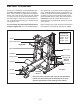
IMPORTANT PRECAUTIONS WARNING: To reduce the risk of serious injury, read the following important precautions before using the weight bench. 1. Read all instructions in this manual before using the weight bench. Use the weight bench only as described in this manual. 11. Never release the butterfly arm, ankle strap, or lat bar while the weights are raised; the weights will fall with great force. 2.
BEFORE YOU BEGIN Thank you for selecting the versatile FREEMOTION® R31 SMITH AND BENCH weight bench. The weight bench offers a selection of weight stations designed to develop every major muscle group of the body. Whether your goal is to tone your body, build dramatic muscle size and strength, or improve your cardiovascular system, the weight bench will help you to achieve the specific results you want.
ASSEMBLY Make sure you have the following tools: Make Assembly Easier for Yourself • Two adjustable wrenches Everything in this manual is designed to ensure that the weight bench can be assembled successfully by most people. Before beginning assembly, make sure to read the information on this page. This brief introduction will save you much more time than it takes to read it.
1 Frame Assembly 1. 28 Before beginning, read the information on page 5. This brief introduction will save much more time than it takes to read it. 3 For help identifying the small parts used in assembly, use the PART IDENTIFICATION CHART in the center of this manual. 28 Attach a Base Cap (28) to a Side Base (3) with two M4 x 20mm Tech Screws (68). Attach another Base Cap to the Side Base in the same manner. 68 2 Decal Repeat this step with the other Side Base (3). 1 2.
4. Attach the Foot Plate (19) to the Center Base (2) with two M10 x 80mm Bolts (84) and two M10 Nylon Locknuts (64). Do not tighten the Locknuts yet. 4 2 19 64 84 5. Align the holes in the Center Base (2) with the holes in the Rear Base (1). Insert two Tall Guide Bumpers (89) and two Carriage Guides (7) into the holes. Note: The indicated holes in the Tall Guide Bumpers are closer to the edge than in the Short Guide Bumpers (not shown).
6. Attach the Center Upright (5) to the Center Base (2) with two M10 x 80mm Bolts (84) and two M10 Nylon Locknuts (64). Do not tighten the Locknuts yet. 6 5 64 84 2 7. Press a 48mm Round Inner Cap (31) into a Storage Tube (27). Attach the Tube to a Support (6) with an M10 x 90mm Bolt (78) and an M10 Washer (65). Slide a Weight Tube Bumper (30) onto the Storage Tube. 7 Attach another Storage Tube (27) to the Support (6) in the same manner.
8. Identify the Rear Joint Plates (25) as shown in the inset drawing. 8 Attach the indicated Support (6) to the right Side Base (3) with two Rear Joint Plates (25), four M10 x 84mm Bolts (75), and four M10 Nylon Locknuts (64). Do not tighten the Locknuts yet. 3 6 Attach the other Support (not shown) to the left Side Base (3) in the same manner. 25 75 3 25 64 9. Identify the Front Joint Plates (24) as shown in the inset drawing.
. Attach the Left Front Upright (90) to the left Support (6) with two M10 x 77mm Bolts (85), two M10 Washers (65), and two M10 Nylon Locknuts (64). Do not tighten the Locknuts yet. 10 64 90 6 65 Repeat this step with the Right Front Upright (not shown). 85 64 65 11. Orient a Slanted Guide Bumper (88) as shown. Attach the Bumper and a Guide Rod (8) to the left Side Base (3) with an M10 x 80mm Bolt (84), two M10 Washers (65), a 7mm Spacer (47), a 12mm Spacer (80), and an M10 Nylon Locknut (64).
12. Identify the Right and Left Safety Spotters (17, 18). 12 Right Left Hook Slide the Left Safety Spotter (18) and a Slide Bumper (39) onto the left Guide Rod (8). Set the hook on the Safety Spotter over a lower hook knob on the Left Front Upright (90). 39 39 18 17 Repeat this step with the Right Safety Spotter (17), the right Guide Rod (8), and the Right Front Upright (4). 4 8 90 8 Hook Knob 13. Orient the Gliders (15) as shown.
16. Attach the Front Top Frame (9) to the Left Front Upright (90) with two Top Joint Plates (26), four M10 x 84mm Bolts (75), and four M10 Nylon Locknuts (64). Make sure the Joint Plates are oriented as shown. Do not tighten the Locknuts yet. 16 64 26 Narrow Side 64 Repeat this step with the Right Front Upright (not shown). 75 9 75 90 17. Press two 48mm Round Inner Caps (31) into the Weight Carriage (14). Slide two Weight Tube Bumpers (30) onto the Weight Carriage.
20. Attach the Rear Top Frame (10) to the Center Upright (5) with two M10 x 77mm Bolts (85), two M10 Washers (65), and two M10 Nylon Locknuts (64). Do not tighten the Locknuts yet. 20 85 65 85 65 Attach the Rear Top Frame (10) to the Front Top Frame (9) with two M10 x 77mm Bolts (85), two M10 Washers (65), and two M10 Nylon Locknuts (64). Do not tighten the Locknuts yet. 10 64 64 5 65 65 9 21.
23. Orient the Locking Bar (35) as shown. 23 90 32 Slide the Weight Bar (32) through the left Glider (15), the Locking Bar (35), and the right Glider. 15 Engage the hooks on the Locking Bar (35) onto the hook knobs on the Front Uprights (4, 90). 4 Hook Knob 35 15 24. Press a 48mm Adapter Bushing (34) into a Barbell Adapter (33). 24 Attach the Barbell Adapter (33) to the Weight Bar (32) with an M10 Large Washer (66) and an M10 x 30mm Button Bolt (79).
27. Wrap the Butterfly Cable (61) under a 90mm Pulley (50). Attach the Pulley to the Small Double “U”-bracket (44) with an M10 x 45mm Bolt (73) and an M10 Nylon Locknut (64). 27 61 50 64 73 44 28. Wrap the Butterfly Cable (61) over a “V”-pulley (51). Attach the “V”-pulley and a Large Cable Trap (52) to the Center Upright (5) with an M10 x 58mm Bolt (81) and an M10 Nylon Locknut (64). Make sure the Cable Trap is oriented to hold the Cable in the groove of the “V”-pulley. 28 52 81 51 61 5 64 29.
31. Wrap the Carriage Cable (62) under a 90mm Pulley (50). Attach the Pulley to the Large Double “U”-bracket (43) with an M10 x 45mm Bolt (73) and an M10 Nylon Locknut (64). 31 62 50 64 73 43 32. Wrap the Carriage Cable (62) over a 90mm Pulley (50). Attach the Pulley inside the Top Frame (10) with an M10 x 77mm Bolt (85), two M10 Washers (65), two 17mm Spacers (49), and an M10 Nylon Locknut (64). 32 64 49 10 65 65 49 50 85 33.
35. Route the Long Cable (63) over a 90mm Pulley (50) and down through the Rear Top Frame (10). Attach the Pulley inside the Top Frame with an M10 x 77mm Bolt (85), two M10 Washers (65), two 17mm Spacers (49), and an M10 Nylon Locknut (64). 35 50 10 49 64 65 63 65 49 85 36. Wrap the Long Cable (63) under a 90mm Pulley (50). Attach the Pulley to the Center Base (2) with an M10 x 73mm Bolt (74). Do not thread a locknut onto the Bolt yet. 36 63 50 2 74 37.
40. Route the Long Cable (63) through the Center Upright (5) and under a 90mm Pulley (50). Attach the Pulley inside the indicated bracket on the Upright with an M10 x 45mm Bolt (73) and an M10 Nylon Locknut (64). 40 63 5 Bracket 64 73 50 41. Attach a 90mm Pulley (50) inside the bracket on the Center Upright (5), and over the Long Cable (63), with an M10 x 45mm Bolt (73) and an M10 Nylon Locknut (64). 41 64 50 63 5 42. Slide a Clip Cover (53) onto the Long Cable (63).
44. Identify the Right and Left Fly Pad (21, 22). Note that the holes are not centered in the pads (see the inset drawing). 44 11 Attach the Left Fly Pad (22) to the Left Fly Arm (11) with two M6 x 20mm Screws (70). 70 12 Attach the Right Fly Pad (21) to the Right Fly Arm (12) in the same manner. 22 21 21 Bench Assembly 22 45 126 45. Press two 63mm Round Outer Caps (116) onto the Bench Stabilizer (95).
48. Press two 40mm x 50mm Inner Caps (115) into the Backrest Frame (99). 48 Attach the Backrest Bracket (100) to the Backrest Frame (99) with two M10 x 75mm Bolts (125) and two M10 Nylon Locknuts (64). 115 99 115 64 125 100 49. Pull out the Bench Knob (118) that is toward the Bench Stabilizer (95). Insert the Backrest Bracket (100) into the Bench Frame (94) as shown. Engage the Knob into a hole in the Backrest Bracket.
51. Attach a Right and Left Leg Lever Pad (107, 108) to a Leg Lever Plate (98) with four M6 x 20mm Screws (70). 51 70 70 Attach the other Right and Left Leg Lever Pads (107, 108) to the other Leg Lever Plate (98) in the same manner. 98 98 107 108 108 52. Grease an M10 x 80mm Bolt (84). Attach the Leg Lever (96) to the Seat Frame (97) with the Bolt and an M10 Nylon Locknut (64). 52 64 97 96 84 Grease 53. Attach the Bench Backrest (106) to the Backrest Frame (99) with four M6 x 20mm Screws (70).
54. Attach the Seat (105) to the Seat Frame (97) with four M6 x 20mm Screws (70). 54 105 97 70 55. Attach the Curl Pad (104) to the Curl Post (103) with two M6 x 20mm Screws (70). 55 104 103 70 56. Attach a Curl Bumper (111) to the Curl Bar (101) with an M4 x 16mm Self-tapping Screw (122) and an M5 Washer (121). 56 Attach the Pin (112) to the Curl Bar (101) with an M4 x 16mm Self-tapping Screw (122). 101 122 111 121 122 112 57. Make sure that all parts have been properly tightened.
ADJUSTMENTS This section explains how to adjust the weight bench. See the EXERCISE GUIDELINES on page 28 for important information about how to get the most benefit from your exercise program. Also, refer to the accompanying exercise guide to see the correct form for each exercise. Make sure all parts are properly tightened each time the weight bench is used. Replace any worn parts immediately. The weight bench can be cleaned with a damp cloth and a mild, non-abrasive detergent. Do not use solvents.
ATTACHING WEIGHTS To use the barbell, slide the desired amount of weight onto the Barbell Adapters (33). Secure the weights with the Weight Clips (60). 14 WARNING: Do not place more than 310 pounds on the barbell. Always place the same amount of weight on each side of the barbell. Always secure weights with the Weight Clips (60). 33 Weights can be secured to the Weight Carriage (14) in the same manner. 60 STORING WEIGHTS Your weights can be stored on the Storage Tubes (27).
ATTACHING THE CURL POST For some exercises, the Curl Post (103) must be attached to the weight bench. Slide the Curl Post into the Seat Frame (97) and secure it with the Curl Knob (113). Fully tighten the Curl Knob. Remove the Curl Post (103) when performing exercises that do not require it. 103 97 113 ATTACHING THE CURL BAR For some exercises, the Curl Bar (101) must be attached to the Leg Lever (96) with the Pin (112). Remove the Curl Bar (101) when performing exercises that do not require it.
TIGHTENING THE CABLES A Woven cable, the type of cable used on the weight bench, can stretch slightly when it is first used. If there is slack in the cables before resistance is felt, the cables should be tightened. Make sure that the cables are not too tight, or the weight carriage will be lifted. 64 See drawing A. Slack can be removed from the cables by moving the 90mm Pulley (50) to a higher set of holes in the Large Double “U”-bracket (43).
CABLE DIAGRAM The cable diagram below shows the proper routing of the Butterfly Cable (61), the Carriage Cable (62), and the Long Cable (63). Use the diagram to make sure that the cables have been assembled correctly. If the cables have not been correctly routed, the weight bench will not function properly and damage may occur. The numbers show the correct route for each cable. Make sure that the cable traps do not touch or bind the cables.
EXERCISE GUIDELINES THE FOUR BASIC TYPES OF WORKOUTS PERSONALIZING YOUR EXERCISE PROGRAM Muscle Building To increase the size and strength of your muscles, push them close to their maximum capacity. Your muscles will continually adapt and grow as you progressively increase the intensity of your exercise. You can adjust the intensity level of an individual exercise in two ways: • by changing the amount of weight used • by changing the number of repetitions or sets performed.
slowly as you stretch and do not bounce. Ease into each stretch gradually and go only as far as you can without strain. Stretching at the end of each workout is an effective way to increase flexibility. Rest for a short period of time after each set. The ideal resting periods are: • Rest for three minutes after each set for a muscle building workout. • Rest for one minute after each set for a toning workout. • Rest for 30 seconds after each set for a weight loss workout.
EXERCISE MONDAY WEIGHT SETS REPS WEIGHT SETS REPS WEIGHT SETS REPS Date: / / AEROBIC EXERCISE TUESDAY Date: / / WEDNESDAY EXERCISE Date: / / THURSDAY AEROBIC EXERCISE Date: / / EXERCISE FRIDAY Date: / / Make photocopies of this page for scheduling and recording your workouts.
EXERCISE MONDAY WEIGHT SETS REPS WEIGHT SETS REPS WEIGHT SETS REPS Date: / / AEROBIC EXERCISE TUESDAY Date: / / WEDNESDAY EXERCISE Date: / / THURSDAY AEROBIC EXERCISE Date: / / EXERCISE FRIDAY Date: / / Make photocopies of this page for scheduling and recording your workouts.
PART IDENTIFICATION CHART—Model No.
M10 x 66mm Bolt (76) M10 x 73mm Bolt (74) M10 x 71mm Carriage Bolt (124) M10 x 75mm Bolt (125) M6 x 76mm Screw (69) M10 x 77mm Bolt (85) M10 x 80mm Bolt (84) M10 x 84mm Bolt (75) M10 x 90mm Bolt (78) M12 x 108mm Bolt (72) M10 x 130mm Bolt (128)
PART LIST—Model No. FMBE39530 Key Qty. No.
17 83 40 41 77 40 47 65 65 4 8 31 88 47 85 85 38 38 39 15 41 83 29 47 68 64 80 64 28 31 65 30 27 30 42 14 27 31 30 65 64 65 64 46 45 6 25 76 64 85 65 65 78 78 64 64 3 24 85 65 64 1 25 64 65 89 47 16 7 39 29 82 43 64 50 31 30 50 64 73 76 65 65 46 42 62 47 24 65 75 75 80 64 74 2 50 69 51 84 68 28 84 50 64 64 79 66 34 53 86 20 33 64 84 84 54 93 13 81 21 52 63 50 19 64 5 51 84 84 64 65 85
EXPLODED DRAWING—Model No.
ORDERING REPLACEMENT PARTS To order replacement parts, call our Customer Service Department toll-free at 1-800-999-3756, Monday through Friday, 6 a.m. until 6 p.m. MST (excluding holidays).