
Owner's Manual


6
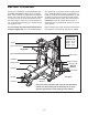
1.
Attach a Base Cap (28) to a Side Base (3) with
two M4 x 20mm Tech Screws (68). Attach anoth-
er Base Cap to the Side Base in the same
manner.
Repeat this step with the other Side Base (3).
2. Attach the Rear Base (1) to a Side Base (3) with
two M10 x 77mm Bolts (85), two M10 Washers
(65), and two M10 Nylon Locknuts (64). Do not
tighten the Locknuts yet. Make sure the warn-
ing decal is in the position shown.
Repeat this step with the other Side Base (3).
3. Attach the Floor Plate (23) to a Side Base (3) with
two M10 x 77mm Bolts (85), two M10 Washers
(65), and two M10 Nylon Locknuts (64). Do not
tighten the Locknuts yet.
Repeat this step with the other Side Base (3).
Before beginning, read the information on
page 5. This brief introduction will save
much more time than it takes to read it.
For help identifying the small parts used in
assembly, use the PART IDENTIFICATION
CHART in the center of this manual.
1
28
28
3
1
85
85
Decal
3
64
65
65
68
3
2
64
65
65
3
3
85
85
23
Frame Assembly