
Owner's Manual


9
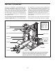
8. Identify the Rear Joint Plates (25) as shown in
the inset drawing.
Attach the indicated Support (6) to the right Side
Base (3) with two Rear Joint Plates (25), four
M10 x 84mm Bolts (75), and four M10 Nylon
Locknuts (64). Do not tighten the Locknuts yet.
Attach the other Support (not shown) to the
left Side Base (3) in the same manner.
9. Identify the Front Joint Plates (24) as shown
in the inset drawing.
Attach the Right Front Upright (4) to the right Side
Base (3) with two Front Joint Plates (24), four
M10 x 84mm Bolts (75), and four M10 Nylon
Locknuts (64). Do not tighten the Locknuts yet.
Note: The Right Front Upright will lean toward
the Support (6).
Attach the Left Front Upright (not shown) to
the left Side Base (3) in the same manner.
8
9
6
3
25
25
25
64
75
3
24
64
24
4
6
3
75
3
24