Model No. FMBE9097.0 Serial No. USER’S MANUAL Write the serial number in the space above for future reference. Serial Number Decal (behind backrest) QUESTIONS? As a manufacturer, we are committed to providing complete customer satisfaction. If you have questions, or if parts are missing, PLEASE DO NOT CONTACT THE STORE; please contact Customer Care.
TABLE OF CONTENTS WARNING DECAL PLACEMENT . . . . . . . . . . . . . . . . . . . . . . . . . . . . . . . . . . . . . . . . . . . . . . . . . . . . . . . . . . . . . 2 IMPORTANT PRECAUTIONS . . . . . . . . . . . . . . . . . . . . . . . . . . . . . . . . . . . . . . . . . . . . . . . . . . . . . . . . . . . . . . . . 3 BEFORE YOU BEGIN . . . . . . . . . . . . . . . . . . . . . . . . . . . . . . . . . . . . . . . . . . . . . . . . . . . . . . . . . . . . . . . . . . . . . . 4 PART IDENTIFICATION CHART . . . . .
IMPORTANT PRECAUTIONS WARNING: To reduce the risk of serious injury, read all important precautions and instructions in this manual and all warnings on the weight system before using the weight system. ICON assumes no responsibility for personal injury or property damage sustained by or through the use of the weight system. 1. Before beginning any exercise program, consult your physician. This is especially important for persons over the age of 35 or persons with pre-existing health problems. 10.
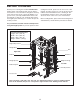
BEFORE YOU BEGIN reading this manual, please see the front cover of this manual. To help us assist you, note the product model number and serial number before contacting us. The model number and the location of the serial number decal are shown on the front cover of this manual. Thank you for selecting the versatile FREEMOTION® weight system. The weight system offers an impressive selection of exercise stations designed to develop every major muscle group of the body.
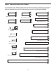
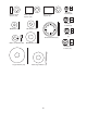
PART IDENTIFICATION CHART See the drawings below to identify small parts used in assembly. The number in parentheses by each drawing is the key number of the part, from the PART LIST near the end of this manual. Note: Some small parts may have been preattached. If a part is not in the parts bag, check to see if it has been preattached.
M10 x 6.
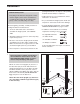
ASSEMBLY packing materials. Do not dispose of the packing materials until assembly is completed. Make Assembly Easier Everything in this manual is designed to ensure that the weight system can be assembled successfully by almost anyone. By setting aside plenty of time, assembly will go smoothly. • Tighten all parts as you assemble them, unless instructed to do otherwise. • As you assemble the weight system, make sure all parts are oriented as shown in the drawings.
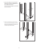
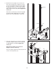
2. Orient a Rear Upright (12) as shown. Attach the Rear Upright to the Base (14) with two M10 x 110mm Screws (116) and two M10 Washers (41). Do not tighten the Screws yet. 2 Attach the other Rear Upright (12) to the Base (14) in the same way. 12 Posts 12 116 41 14 3. Attach a Floor Guard (78) to the the Base (14) with two M4 x 20mm Self-tapping Screws (120). 3 Attach the remaining three Floor Guards (78) to the Base (14) in the same way.
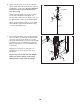
4. Orient the Center Upright (13) as shown and insert it into the Base (14). Hold the Foot Plate (15) and the Weight Carriage Base (20) against the Base. Attach the Foot Plate, Center Upright, and Weight Carriage Base to the Base with two M10 x 110mm Screws (116). Do not tighten the Screws yet. 4 Bracket Attach the Foot Plate (15) to the Center Upright (13) with an M10 x 93mm Bolt (117), an M10 Washer (41), and an M10 Nylon Locknut (37). 13 37 41 20 117 14 116 15 5.
6. Attach the Left Spotter Hook (115) to a Barbell Spotter (109) with an M10 x 25mm Bolt (10) and an M10 Nylon Locknut (37). Do not overtighten the Nylon Locknut; the Left Spotter Hook must pivot easily. 6 104 Long End 37 Identify a Barbell Guide (112), which is slightly shorter than a Weight Carriage Guide (not shown). Slide a Barbell Spotter Bumper (111) and the Barbell Spotter (109) onto the Barbell Guide. 107 109 10 115 Orient a Barbell Carriage (104) as shown.
8. Attach a Barbell Guide (112) to the Top Frame (17) with an M10 x 55mm Bolt (119), two M10 Washers (41), two M10 x 6.5mm Spacers (38), and an M10 Nylon Locknut (37). 8 Attach the other Barbell Guide (not shown) to the Top Frame (17) in the same way. 37 41 38 See steps 2, 4 and 5. Tighten the M10 x 110mm Screws (116). 38 17 119 41 112 9. Attach a Weight Carriage Guide (21) to the Weight Carriage Base (20) with an M10 x 55mm Bolt (119), two M10 Washers (41), two M10 x 6.
11. Attach the Weight Carriage Frame (18) to the Weight Carriage Guides (21) with two M8 x 40mm Bolts (52) and two M8 Nylon Locknuts (8). Do not tighten the Nylon Locknuts yet. 11 8 18 52 21 12. Locate the indicated holes inside the Center Upright (13). Insert an M10 x 25mm Screw (118) into the lower hole, and tighten the Screw into the Weight Carriage Frame (18). Next, tighten an M10 x 25mm Screw into the upper hole. 12 95 17 18 118 13 Press a 75mm Square Inner Cap (95) into the Top Frame (17).
14. Grease the bottom of the Right Adjustment Bracket (24), and slide the Right Arm (23) onto the Right Adjustment Bracket. See the inset drawing. Orient two Bracket Retainers (73) so that the teeth bend downward. Tap the Bracket Retainers onto the Right Adjustment Bracket. 14 36 35 44 Attach the Right Arm (23) to Right Adjustment Bracket (24) with an M10 x 30mm Screw (54), an M10 Lock Washer (86), an M10 Large Washer (7), and a Bushing Cap (88).
17. Orient the Locking Bar (114) as shown. Hold the Locking Bar between the left Barbell Carriage (104) and the right Barbell Carriage (not shown). Insert the Barbell (113) into the left Barbell Carriage, the Locking Bar, and the right Barbell Carriage. Center the Barbell in the Barbell Carriages. Then, engage the Locking Bar into slots in the Front Uprights (11). 17 104 113 114 11 18. Attach a Barbell Adapter (102) to the Barbell (113) with an M10 x 25mm Screw (118) and a Large Washer (53).
20. Tighten three Weight Storage Tubes (67) onto a Rear Upright (12). 20 Attach the remaining three Weight Storage Tubes (not shown) onto the other Rear Upright (12) in the same way. 67 12 12 67 67 21. Attach an Upright Pin/Tether (28) to a Weight Rest (26) with an M4 x 16mm Self-tapping Screw (42). Hold the Weight Rest against one of the Front Uprights (11), and fully insert the Upright Pin into the Weight Rest and into one of the holes in the Front Upright.
22. See the CABLE DIAGRAM on page 29 to identify the cables as you assemble them. 22 Grease 45 Identify the Arm Cable (43). Grease an M8 x 22mm Shoulder Bolt (45). Attach the Arm Cable to the Left Adjustment Bracket (25) with the Shoulder Bolt and an M8 Nylon Locknut (8). Make sure that the flat edge of the cable is against the Left Adjustment Bracket. Do not overtighten the Shoulder Bolt; the Arm Cable must pivot easily. 43 8 25 45 43 25 8 23.
25. Wrap the Arm Cable (43) over a “V”-pulley (75). Attach the “V”-pulley, a Large Cable Trap (77), and two Full Pulley Guards (76) to the other side of the bracket on the Center Upright (13) with an M10 x 60mm Bolt (55) and an M10 Nylon Locknut (37). Make sure that the Large Cable Trap is oriented to hold the Arm Cable in the groove of the “V”-pulley. 25 55 76 75 77 43 76 37 13 26. Grease an M8 x 22mm Shoulder Bolt (45).
28. Wrap the High Cable (81) around a Small Pulley (74). Attach the Small Pulley to the Top Frame (17) with an M10 x 45mm Bolt (48) and an M10 Nylon Locknut (37). 28 48 17 37 74 81 29. Feed the High Cable (81) through the indicated slot in the Top Frame (17). Wrap the High Cable around a Small Pulley (74). Attach the Small Pulley to the Top Frame with an M10 x 45mm Bolt (48) and an M10 Nylon Locknut (37). 29 48 Slot 17 81 74 37 30. Wrap the High Cable (81) over a Small Pulley (74).
31. Wrap the High Cable (81) under a Small Pulley (74). Attach the Small Pulley, a Small Cable Trap (93), and two Half Pulley Guards (91) to the second hole from the top of the “U”-bracket (34) with an M10 x 48mm Bolt (121) and an M10 Nylon Locknut (37). Make sure that the Small Cable Trap and the Half Pulley Guards are oriented as shown. 31 81 74 93 37 91 121 32. Wrap the High Cable (81) over a Small Pulley (74).
33. Feed the High Cable (81) through the indicated slot in the Top Frame (17). Wrap the High Cable around a Small Pulley (7). Attach the Small Pulley to the Top Frame with an M10 x 45mm Bolt (48) and an M10 Nylon Locknut (37). 33 48 17 74 37 81 34. See the inset drawing. Insert the cabling rod into the left Swivel Bracket (31) and the Top Frame (17). Attach the cabling rod to the High Cable (81). Then, pull the cabling rod and the High Cable out of the Swivel Bracket.
35. Wrap the High Cable (81) over a Large Pulley (4). Attach the Large Pulley inside the Swivel Bracket (31) with an M10 x 55mm Bolt (119), two M10 Washers (41), two M10 x 6.5mm Spacers (38), and an M10 Nylon Locknut (37). 35 Remove the M8 Jamnut (2) from the High Cable (81), and slide the Cable Stop (6) onto the Cable. Next, tighten the Jamnut onto the Cable as far as possible, tighten the Cable Eyelet (5) onto the Cable as far as possible, and then tighten the Jamnut against the Cable Eyelet.
38. Wrap the Rear Cable (94) under a Small Pulley (74). Attach the Small Pulley, a Small Cable Trap (93), and two Half Pulley Guards (91) at the second hole from either end of the two Pulley Plates (92) with an M10 x 48mm Bolt (121) and an M10 Nylon Locknut (37). Make sure that the Small Cable Trap and the Half Pulley Guards are oriented as shown. 38 91 94 74 37 93 91 92 39.
41. Wrap the Low Cable (80) over a Small Pulley (74). Attach the Small Pulley and two Half Pulley Guards (91) to the Double “U”-bracket (98) with an M10 x 45mm Bolt (48) and an M10 Nylon Locknut (37). Make sure that the Half Pulley Guards are oriented as shown. 41 98 91 37 74 48 91 80 42. Route the Low Cable (80) through the Weight Carriage Base (20) as shown. Attach two Small Pulleys (74) inside the Weight Carriage Base with two M10 x 55mm Bolts (119), four M10 Washers (41), four M10 x 6.
44. Wrap the Low Cable (80) under a Small Pulley (74). Attach the Small Pulley and two Half Pulley Guards (91) to the Weight Carriage Base (20) with an M10 x 45mm Bolt (48) and an M10 Nylon Locknut (37). Make sure that the Half Pulley Guards are oriented as shown. 44 80 74 91 91 37 48 20 45. Attach the Low Cable (80) to the “U”-bracket (34) with an M8 Nylon Locknut (8) and an M8 Washer (32) (see the inset drawing). Tighten the Nylon Locknut exactly two full turns onto the Low Cable.
ADJUSTMENT This section explains how to adjust the weight system. See the EXERCISE GUIDELINES on page 30 for important information about how to get the most benefit from your exercise program. Also, refer to the accompanying exercise guide to see the correct form for several exercises. USING THE WEIGHT RESTS AND THE WEIGHT SPOTTERS Before using a separate barbell (not included), set the Weight Spotters (29) at the lowest point to which you want your barbell to move.
USING THE LOCKING BAR Grip the Locking Bar (114) with both hands. Turn the Locking Bar until the two hooks disengage the slots in the Front Uprights (11). Raise or lower the Locking Bar to a new position and turn it until the hooks engage slots in the Front Uprights. Hook 11 114 11 ADJUSTING THE ARMS To change the position of the Right Arm (23), pull the Arm Knob (85) out of the Right Adjustment Bracket (24).
ATTACHING THE ACCESSORIES TO THE HIGH PULLEY STATION To use the high pulley station, first place the desired weights on the weight carriage (see ADDING WEIGHTS TO THE BARBELL OR THE WEIGHT CARRIAGE on page 26). Next, attach the Lat Bar (58) to the High Cable (81) with a Cable Clip (63). For some exercises, the Chain (3) should be attached between the Lat Bar and the Cable with two Cable Clips.
MAINTENANCE Make sure that all parts are properly tightened each time the weight system is used. Replace any worn parts immediately. The weight system can be cleaned with a damp cloth and a mild, non-abrasive detergent; do not use solvents to clean the weight system. TIGHTENING THE CABLES Woven cable, the type of cable used on the weight system, can stretch slightly when it is first used. If there is slack in the cables before resistance is felt, the cables should be tightened.
CABLE DIAGRAM The diagram below shows the proper routing of the cables. The numbers in each drawing show the proper routing for that cable. Use the diagram to make sure that the cables, cable traps, and pulley guards are assembled correctly. If the cables, cable traps, and pulley guards are not assembled correctly, the weight system will not function properly and damage may occur. Make sure that the cable traps do not touch or bind the cables. 2 6 2 3 4 5 3 7 High Cable (81) Length: 21 ft. 9 in. (6.
EXERCISE GUIDELINES THE FOUR BASIC TYPES OF WORKOUTS PERSONALIZING YOUR EXERCISE PROGRAM Muscle Building To increase the size and strength of your muscles, push them close to their maximum capacity. Your muscles will continually adapt and grow as you progressively increase the intensity of your exercise. You can adjust the intensity level of an individual exercise in two ways: • by changing the amount of resistance used • by changing the number of repetitions or sets performed.
COOLING DOWN The repetitions in each set should be performed smoothly and without pausing. The exertion stage of each repetition should last about half as long as the return stage. Proper breathing is important. Exhale during the exertion stage of each repetition and inhale during the return stroke. Never hold your breath. End each workout with 5 to 10 minutes of stretching. Include stretches for both your arms and legs. Move slowly as you stretch and do not bounce.
MONDAY Date: / / TUESDAY Date: / / WEDNESDAY Date: / / THURSDAY Date: / / FRIDAY Date: / EXERCISE WEIGHT SETS REPS WEIGHT SETS REPS WEIGHT SETS REPS AEROBIC EXERCISE EXERCISE AEROBIC EXERCISE EXERCISE / Make photocopies of this page for scheduling and recording your workouts.
NOTES 33
NOTES 34
PART LIST—Model No. FMBE9097.0 Key No. Qty. 1 2 3 4 5 6 7 8 9 10 11 12 13 14 15 16 17 18 19 20 21 22 23 24 25 26 27 28 29 30 31 32 33 34 35 36 37 38 39 40 41 42 43 44 45 46 47 48 49 50 2 3 1 3 3 3 4 5 2 2 2 2 1 1 1 2 1 1 1 1 2 1 1 1 1 2 2 4 2 2 2 1 4 1 2 2 32 24 2 2 43 4 1 2 2 2 4 7 4 2 Description R0907A Key No. Qty.
Key No. Qty. 101 102 103 104 105 106 107 108 109 110 111 112 113 114 2 2 2 2 4 4 2 4 2 1 2 2 1 1 Description Key No. Qty.
EXPLODED DRAWING A—Model No. FMBE9097.
EXPLODED DRAWING B—Model No. FMBE9097.
EXPLODED DRAWING C—Model No. FMBE9097.
ORDERING REPLACEMENT PARTS To order replacement parts, please see the front cover of this manual. To help us assist you, be prepared to provide the following information when contacting us: • the model number and serial number of the product (see the front cover of the manual) • the name of the product (see the front cover of this manual) • the key number and description of the part(s) (see the PART LIST and the EXPLODED DRAWING near the end of this manual) LIMITED WARRANTY ICON Health & Fitness, Inc.