
Owner's Manual

10
6
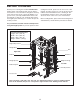
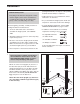
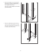
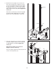
7. Insert the Barbell Guide (112) into the indicated
hole in the Base (14). Next, lift the Barbell Guide
up into the hole in the Top Frame (not shown).
Attach the Barbell Guide to the Base with an M10
x 55mm Bolt (119), two M10 Washers (41), two
M10 x 6.5mm Spacers (38), and an M10 Nylon
Locknut (37).
Engage the Left Spotter Hook (115) into an
adjustment slot near the bottom of the Front
Upright (11).
Repeat steps 6 and 7 with the other Barbell
Guide (not shown). Always position both
Barbell Spotters (109) at the same height.
7
14
11
37
41
41
119
38
38
Hole
115
115
10
37
1
09
111
107
104
112
Long End
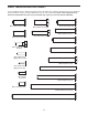
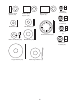
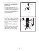
6. Attach the Left Spotter Hook (115) to a Barbell
S
potter (109) with an M10 x 25mm Bolt (10) and
an M10 Nylon Locknut (37). Do not overtighten
t
he Nylon Locknut; the Left Spotter Hook
must pivot easily.
Identify a Barbell Guide (112), which is slightly
s
horter than a Weight Carriage Guide (not
s
hown). Slide a Barbell Spotter Bumper (111) and
the Barbell Spotter (109) onto the Barbell Guide.
Orient a Barbell Carriage (104) as shown. Slide a
Barbell Bumper (107) and the Barbell Carriage
onto the Barbell Guide (112).
109
112