
Owner's Manual

7
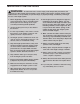
Before beginning assembly, carefully read the fol-
lowing information and instructions:
• To hire an authorized service technician to
assemble the weight system, call 1-800-445-
2480.
• Assembly requires two persons. Some steps may
require three persons.
• Because of its size, the weight system should be
assembled in the location where it will be used.
Make sure that there is enough clearance to walk
around the weight system as you assemble it.
• Place all parts in a cleared area and remove the
packing materials. Do not dispose of the packing
materials until assembly is completed.
• Tighten all parts as you assemble them, unless
instructed to do otherwise.
• As you assemble the weight system, make sure
all parts are oriented as shown in the drawings.
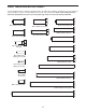
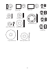
• For help identifying small parts, use the PART
IDENTIFICATION CHART on pages 5 and 6.
• In addition to the included tools, assembly
requires the following tools (not included):
two adjustable wrenches
one rubber mallet
one standard screwdriver
one Phillips screwdriver
Some assembly steps also require a socket set
with an extension.
ASSEMBLY
M
ake Assembly Easier
E
verything in this manual is designed to ensure
that the weight system can be assembled suc-
cessfully by almost anyone. By setting aside
plenty of time, assembly will go smoothly.
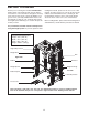
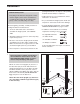
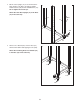
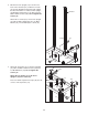
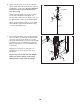
1.
Orient one of the Front Uprights (11) and one of
the Base Feet (16) as shown. Attach the Front
Upright and the Base Foot to the Base (14) with
two M10 x 155mm Screws (79). Then, orient a
38mm x 100mm Large Outer Cap (99) so that the
thick end is at the bottom
(see the inset draw-
ing), and press it onto the Base Foot.
Attach the other Front Upright (11), Base Foot
(16), and 38mm x 100mm Large Outer Cap (99)
in the same way.
1
1
1
11
14
16
79
Hole
Holes
Large Hole
99
99
Thick
End
Before beginning assembly, read the impor-
tant information in the box above. See the
PART IDENTIFICATION CHART on pages 5
and 6 for help identifying small parts.
99
16