Model No. FMTK7256P.3/ FMTK7506P.3 Serial No. Write the serial number in the space above for future reference. USERʼS MANUAL Serial Number Decal QUESTIONS? If you have questions, or if parts are damaged or missing, please see HOW TO CONTACT CUSTOMER CARE on the back cover of this manual. CAUTION Read all precautions and instructions in this manual before using this equipment. Keep this manual for future reference. www.freemotionfitness.
TABLE OF CONTENTS IMPORTANT PRECAUTIONS . . . . . . . . . . . . . . . . . . . . . . . . . . . . . . . . . . . . . . . . . . . . . . . . . . . . . . . . . . . . . . . . .3 WARNING DECAL PLACEMENT . . . . . . . . . . . . . . . . . . . . . . . . . . . . . . . . . . . . . . . . . . . . . . . . . . . . . . . . . . . . . .5 BEFORE YOU BEGIN . . . . . . . . . . . . . . . . . . . . . . . . . . . . . . . . . . . . . . . . . . . . . . . . . . . . . . . . . . . . . . . . . . . . . . .6 ASSEMBLY . . . . . . . . . . .
IMPORTANT PRECAUTIONS WARNING: To reduce the risk of serious injury, read all important precautions and instructions in this manual and all warnings on your incline trainer before using your incline trainer. FreeMotion Fitness assumes no responsibility for personal injury or property damage sustained by or through the use of this product. 1. It is the responsibility of the owner to ensure that all users of the incline trainer are adequately informed of all warnings and precautions. 10.
22. Make sure to perform all maintenance procedures outlined in this manual. Failure to do so will void the warranty and may result in damage to the incline trainer. 18. The pulse sensor is not a medical device. Various factors, including the user's movement, may affect the accuracy of heart rate readings. The pulse sensor is intended only as an exercise aid in determining heart rate trends in general. 23. 19. Never leave the incline trainer unattended while it is running. 20.
WARNING DECAL PLACEMENT These drawings show the location(s) of the warning decal(s). If a decal is missing or illegible, see the back cover of this manual and request a free replacement decal. Apply the decal in the location shown. Note: The decal(s) may not be shown at actual size. : HIGH VOLTAGE Disconnect line cord from outlet before servicing. HAZARDOUS VOLTAGE Disconnect power before servicing.
BEFORE YOU BEGIN after reading this manual, please see the back cover of this manual. To help us assist you, note the product model number and serial number before contacting us. The model number and the location of the serial number decal are shown on the front cover of this manual. Thank you for selecting the revolutionary FREEMOTION® INCLINE TRAINER. The INCLINE TRAINER provides an impressive selection of features designed to make your workouts at home more effective and enjoyable.
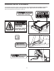
ASSEMBLY Assembly requires two persons. Set the incline trainer in a cleared area and remove all packing materials. Do not dispose of the packing materials until assembly is completed. Assembly can be completed using a 3/8" hex key, a 7/32" hex key, and a Phillips screwdriver. For help identifying assembly hardware, see the drawings below. Note: If a part is not found in the hardware kit, check to see if the part has been preattached. To avoid damaging plastic parts, do not use power tools for assembly.
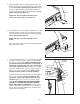
2. Slide the Uprights (93) onto the Base Frame (56), and align the holes in the Uprights with the holes in the Base Frame. Be careful to avoid pinching the wires. Finger tighten two Side Base Bolts (95) through the bracket near the right Upright and into the Base Frame; do not tighten the Side Base Bolts yet. 2 93 Repeat this step on the left side of the incline trainer; there are no wires on the left side. 95 56 3.
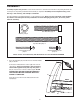
5. With the help of a second person, pivot the console assembly to the position shown. Be careful to avoid pinching your hands or the wires. 5 102 Align the Handrail Bolts (102) with the holes in the tops of the Uprights (93). Start all four Handrail Bolts, and then firmly tighten them. Console Assembly 102 93 6.
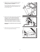
8. Attach the Front Cover (17) to the Frame (22) with the two Cover Screws (2) and the four Front Cover Screws (16). 8 22 2 16 16 17 9. Make sure that all parts are properly tightened before you use the incline trainer. To protect the floor or carpet, place a mat beneath the incline trainer. If you purchase the Workout TV console, follow the steps below to assemble the console. 1. Unplug the power cord. Remove the four Console Plate Screws (94) and the Basic Console Plate (not shown).
HOW TO MOVE THE INCLINE TRAINER Before moving the incline trainer, unplug the power cord. Note: It may be necessary to disconnect a CATV cable and a network wire from the incline trainer, depending on how far the incline trainer will be moved. Due to the size and weight of the incline trainer, moving it requires two or three persons. Hold the metal frame firmly in the location shown at the right.
HOW TO CONNECT THE INCLINE TRAINER DANGER: Improper connection of HOW TO CONNECT THE POWER CORD IN THE UK This product must be earthed. If it should malfunction or break down, earthing provides a path of least resistance for electric current to reduce the risk of electric shock. the equipment-grounding conductor can result in an increased risk of electric shock. Check with a qualified electrician or serviceman if you are in doubt as to whether the product is properly grounded.
HOW TO UPGRADE THE CONSOLE Your incline trainer has been pre-configured to operate with the Basic console or the Workout TV console (see the drawings below). To learn about the features of the Basic console, see page 14. To learn about the features of the Workout TV console, see the userʼs manual included with the Workout TV console. To upgrade your console and expand the capabilities of the incline trainer whenever you choose, please see the back cover of this manual.
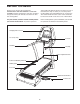
HOW TO USE THE BASIC CONSOLE Note: If there is a sheet of clear plastic on the face of the console, remove it. Matrix Main Display FEATURES OF THE CONSOLE to keep your heart rate near target levels during your workouts, and three unique FITNESS TEST programs that measure your relative fitness level. Note: The HEART RATE programs and the FITNESS TEST programs require the use of a Polar®-compatible chest pulse sensor (not included).
OVERVIEW OF THE CONSOLE The DISPLAY LOCK button—This button can be used during your workout to keep the main display from scanning from one number to the next every few seconds. Each time the DISPLAY LOCK button is pressed during your workout, the word LOCKED or UNLOCKED will briefly appear in the main display. For your benefit, please read all of the instructions on pages 15 and 16 before you use the incline trainer. THE BUTTONS The CLEAR button—This button is used to reset the console.
CAUTION: Pulse/% Max—When you use the handgrip pulse sensor or a Polar®-compatible chest pulse sensor (not included), this section of the main display will show your heart rate. When a HEART RATE program is selected, the display will show your heart rate and the corresponding percentage of your age-predicted maximum heart rate (see step 7 on page 22 for an explanation of your age-predicted maximum heart rate). The display will change from one number to the other every few seconds.
GETTING STARTED HOW TO USE THE QUICK START MODE 1. Plug in the power cord. If you do not plan to use a program, the QUICK START mode will allow you to simply start exercising and adjust the speed and incline of the incline trainer manually. See HOW TO CONNECT THE POWER CORD on page 12. 2. Move the on/off circuit breaker to the “on” position. Locate the on/off circuit breaker on the incline trainer near the power cord. Switch the on/off circuit breaker to the “on” position. 1.
4. Follow your progress with the matrix and the main display. HOW TO USE A MANUAL PROGRAM The MANUAL TIME program allows you to enter a time goal for your workout. The program will then count down the time remaining in your workout as you control the speed and incline of the incline trainer. The matrix will show your progress and the incline settings that you select. When you begin exercising, the left column of the matrix will begin to flash.
4. Enter your weight. To stop the walking belt, press the STOP button. The time will begin to flash in the main display. To restart the walking belt, press the QUICK START button or the SPEED + button and then adjust the speed as desired. Next, the words ENTER WEIGHT and a weight setting of 185 pounds will appear in the main display. To enter your weight, press the + and – buttons beside the ENTER button; hold down the buttons to enter your weight quickly.
HOW TO USE A FITNESS TEST PROGRAM 3. Select a FITNESS TEST program. The FITNESS TEST programs measure your approximate VO2 max, or aerobic capacity. VO2 max is a measure of your ability to take in and utilize oxygen to generate energy for endurance activities such as running and cycling. In technical terms, VO2 max is the maximum volume of oxygen, in milliliters, that your body can use in one minute, per kilogram of body weight. A high VO2 max indicates a high level of cardiorespiratory fitness.
6. Enter your gender. When the EBBELING FITNESS TEST is completed, the walking belt will slow to a stop and your VO2 max will be shown in the main display. If you selected the EBBELING FITNESS TEST, you will be prompted to enter your gender. Either the word MALE or the word FEMALE will appear in the main display. To enter your gender, press the + and – buttons beside the ENTER button. When your gender is shown, press the ENTER button.
HOW TO USE A HEART RATE PROGRAM 4. Enter your age. HEART RATE programs automatically control the speed and incline of the incline trainer to keep your heart rate near a target level while you exercise. Follow the steps below to use a HEART RATE program. See step 3 on page 18. 5. Enter your weight. See step 4 on page 19. 1. Put on a Polar®-compatible chest pulse sensor (not included). If you have selected the VARIABLE HEART RATE program, continue to step 6.
8. Enter a program time. next segment. The speed and/or incline setting will flash in the main display to alert you before the speed and/or incline changes. The program will continue until no time remains in the program. The walking belt will then slow to a stop. The words ENTER TIME and a time setting of 15 minutes will appear in the main display. To change the length of time that the program will last, press the + and – buttons beside the ENTER button. Then, press the ENTER button.
HOW TO USE AN INTERVAL PROGRAM 6. Enter a minimum incline setting. The INTERVAL programs will automatically adjust the incline of the walking belt as they guide you through an effective interval training workout. The words MIN INCLINE and the minimum incline setting will appear in the main display. To enter the minimum incline you want to walk or run during your workout, press the + and – buttons beside the ENTER button; hold down the buttons to enter the minimum incline quickly.
Note: You can manually override the incline setting for the current segment by pressing the INCLINE buttons. Every few times an INCLINE button is pressed, an additional indicator will light or darken in the flashing column. (If any of the columns to the right of the flashing column have the same number of lit indicators as the flashing column, an additional indicator may light or darken in those columns as well.
HOW TO USE A WALK/RUN PROGRAM 4. Enter your weight. The 5K program is designed to help you train for a 5K race. See step 4 on page 19. If you have selected the 5K or 10K program, skip to step 6. If you have selected the CROSS COUNTRY program, continue to step 5. The 10K program is designed to help you train for a 10K race. 5. Enter a distance goal. The CROSS COUNTRY program is designed to help you train for a race of a length of your choice.
HOW TO USE A TERRAIN PROGRAM 6. Enter a maximum incline setting. During the HILL program, the incline of the incline trainer will depend on the vertical distance goal and the speed setting that you set. The incline will remain constant with only minor adjustments throughout the program to help you reach your vertical distance goal. The words MAX INCLINE and the incline setting will appear in the main display.
HOW TO USE A FITNESS OR RANDOM PROGRAM 4. Enter your weight. The FITNESS program controls the speed and incline of the incline trainer to create a workout with a warmup period, a steady workout, and a cool-down period. See step 4 on page 19. If you have selected a RANDOM program, continue to step 5. If you have selected a FITNESS program, skip to step 7. The RANDOM program creates a different incline program every time it is selected for a variety of workouts. 5. Enter a maximum incline setting. 1.
HOW TO USE A CUSTOM PROGRAM Each CUSTOM program is divided into several segments. One speed setting and one incline setting is programmed for each segment. (The same speed and/or incline setting may be programmed for two or more consecutive segments.) The incline setting for the first segment is shown in the flashing column of the matrix. The incline settings for the next several segments are shown in the columns to the right. 1. Insert the key into the console. See GETTING STARTED on page 17. 2.
HOW TO USE THE MAINTENANCE MODE 5. Press the ENTER button again and set the delay time for the timeout mode. The console features a maintenance mode that allows you to access information and to view and change various default settings. Follow the steps below to use the maintenance mode. Any time that the incline trainer is not used for several minutes, the console will enter a timeout mode and the words SELECT PROGRAM TO BEGIN will appear in the main display.
7. Press the ENTER button again and set the delay time for the sleep timeout mode. Enter a name for the program. The name can have up to twelve characters, including spaces. To enter a name, press the + and – buttons beside the ENTER button until the desired character appears in the display. Then, press the ENTER button. If you select the wrong character, press the CLEAR button. Continue entering a name in this way. Then, press the ENTER button.
HOW TO DISABLE THE SAFETY KEY To allow the INCLINE TRAINER to be used without the safety key, press the + or – button until the words SAFETY KEY DISABLED appear. Note: The next time the key is inserted into the console, the safety key will automatically be enabled and the console will require the use of the safety key again. If your INCLINE TRAINER is connected to a 120-volt circuit, you can disable the safety key so the INCLINE TRAINER does not require the use of a key.
PREVENTIVE MAINTENANCE Regular maintenance is necessary for optimal performance and long life of the incline trainer. Please read and follow all instructions below. If the incline trainer is not maintained as described, components may wear excessively, the incline trainer may be damaged, and the warranty will be voided. If you have questions about maintenance, please see the back cover of this manual.
TURNING THE WALKING PLATFORM Both sides of the walking platform are designed to be used as walking surfaces. Inspect the walking platform periodically for wear. If there is any wood showing through the phenolic coating, or if the surface is damaged, the walking platform should be turned over. The walking platform will need to be turned over and the walking belt replaced (see page 35) after every 16,000 to 24,000 kilometers (10,000 to 15,000 miles).
REPLACING THE WALKING BELT When the walking belt becomes worn, it should be replaced. The walking belt will need to be replaced after every 16,000 to 24,000 kilometers (10,000 to 15,000 miles). See the Service Manual for replacement instructions. Please see the back cover of this manual to order a new walking belt. REPLACING THE WALKING PLATFORM When both sides of the walking platform become worn, the walking platform should be replaced.
SIX-MONTH PREVENTIVE MAINTENANCE RECORD Photocopy this form and use it to record the preventive maintenance performed on the incline trainer. Each copy of the form can be used for six months (26 weeks). When maintenance is performed, write the date in the appropriate spaces. Make sure to perform each maintenance procedure as described on pages 33 to 35. If the procedures are not performed as described, components may wear excessively, the incline trainer may be damaged, and the warranty will be voided.
TROUBLESHOOTING Most incline trainer problems can be solved by following the steps below. Find the symptom that applies, and follow the steps listed. If further assistance is needed, please see the back cover of this manual. 1. SYMPTOM: THE POWER DOES NOT TURN ON a. Make sure that the power cord is plugged into a properly grounded outlet. (See page 12.) b. Make sure that the key is inserted into the console. c. Check the on/off circuit breaker located on the incline trainer near the power cord.
4. SYMPTOM: THE WALKING BELT IS OFF-CENTER OR SLIPS WHEN WALKED ON a. If the walking belt has shifted to the right: Remove the key and unplug the power cord. Using a 7/32" hex key, turn the roller adjustment bolts in the directions shown, 1/4 of a turn each. Be careful not to overtighten the walking belt. Then, plug in the power cord, insert the key, and use the incline trainer for a few minutes. Repeat until the walking belt is centered. b.
EXERCISE GUIDELINES WARNING: Burning Fat—To burn fat effectively, you must exercise at a low intensity level for a sustained period of time. During the first few minutes of exercise, your body uses carbohydrate calories for energy. Only after the first few minutes of exercise does your body begin to use stored fat calories for energy. If your goal is to burn fat, adjust the intensity of your exercise until your heart rate is near the lowest number in your training zone.
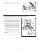
SUGGESTED STRETCHES The correct form for several basic stretches is shown at the right. Move slowly as you stretch—never bounce. 1 1. Toe Touch Stretch Stand with your knees bent slightly and slowly bend forward from your hips. Allow your back and shoulders to relax as you reach down toward your toes as far as possible. Hold for 15 counts, then relax. Repeat 3 times. Stretches: Hamstrings, back of knees and back. 2 2. Hamstring Stretch Sit with one leg extended.
NOTES 41
PART LIST— Model No. FMTK7256P.3/FMTK7506P.3 Key No. Qty. 1 2 3 4 5 6 7 8 9 10 11 12 13 14 15 16 17 18 19 20 21 22 23 24 25 26 27 28 29 30 31 32 33 34 35 36 37 38 39 40 41 42 43 44 45 46 47 48 49 50 2 6 4 6 18 2 2 2 2 4 1 1 1 2 1 12 1 1 2 2 1 1 1 2 2 1 2 1 1 2 1 1 2 8 10 1 4 2 2 2 2 4 4 4 1 2 1 2 2 2 Description Key No. Qty.
Key No. Qty. 101 102 103 104 105 106 107 108 109 110 111 112 113 114 115 116 117 118 119 120 121 122 123 124 125 126 127 128 129 130 131 132 133 134 * * 2 4 1 2 1 4 2 4 1 1 1 1 1 2 1 12 1 1 1 2 2 1 1 4 1 6 5 1 1 6 1 1 1 1 – – Description Key No. Qty.
16 44 30 28 27 131 25 24 21 30 10 4 2 16 3 27 26 32 25 4 3 1 24 10 5 8 7 6 4 23 9 22 11 97 20 5 4 3 107 14 13 12 114 2 4 19 97 5 3 5 20 18 6 16 8 7 5 114 17 2 1 5 107 2 14 5 4 9 19 16 EXPLODED DRAWING A— Model No. FMTK7256P.3/FMTK7506P.
33 34 33 36 82 81 45 85 34 79 37 39 91 85 80 87 130 89 38 41 48 47 126 87 45 43 42 85 127 128 129 15 86 40 46 49 127 89 35 126 120 43 44 50 125 120 87 53 122 126 42 84 81 52 5 80 121 42 43 78 64 121 66 56 77 65 39 37 89 41 55 38 40 54 79 83 44 88 68 54 62 72 74 119 55 63 34 58 57 76 72 69 61 75 90 73 71 70 58 57 59 90 60 EXPLODED DRAWING B— Model No. FMTK7256P.3/FMTK7506P.
95 93 124 51 92 46 34 108 124 96 51 96 92 95 124 113 31 34 95 108 86 111 116 116 16 116 TV CONSOLE 16 67 16 16 94 16 116 BASIC CONSOLE 112 16 116 116 118 29 94 94 116 94 94 94 EXPLODED DRAWING C— Model No. FMTK7256P.3/FMTK7506P.
104 85 85 85 103 102 109 105 100 101 98 104 99 99 106 100 98 106 47 110 102 106 114 85 85 116 116 106 117 116 100 101 116 98 99 116 99 100 98 116 116 116 133 134 123 115 EXPLODED DRAWING D— Model No. FMTK7256P.3/FMTK7506P.
HOW TO CONTACT CUSTOMER CARE If you have questions after reading this manual, or if parts are damaged or missing, please contact Customer Care at one of the phone numbers or addresses listed below. Please note the model number, serial number, and name of the product (see the front cover of this manual) before contacting Customer Care. If you are ordering replacement parts, please also note the key number and description of each part (see the PART LIST and the EXPLODED DRAWING near the end of this manual).