
Owner's Manual

10
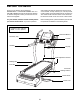
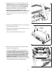
6. Set the console assembly on the Upright (93). Be care-
ful not to pinch any wires. Make sure that the ends
of the Console Crossbar (110) are inserted into the
ends of the Upright.
Start two 3/8" x 2 1/2" Bolts (61) with two 3/8" Flat
Washers (78) and two 3/8" x 2 1/2" Bolts (61) with two
3/8" Star Washers (66) as shown. Do not fully tighten
the Bolts yet.
93
61
66
66
61
61
61
78
78
6
Console
Assembly
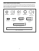
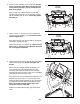
7. Start four 5/16" x 1" Screws (51) into the Upright (93)
and the Console Crossbar (110); start all four Screws,
and then tighten them.
Next, tighten four #8 x 3/4" Screws (86) into the Upright
(93) and the console assembly.
Tighten the four 3/8" x 2 1/2" Bolts (61). Make sure that
the four #8 x 1" Screws (91) are tightened. Be careful
not to overtighten the Screws.
51
93
86
86 86
86
61
61
91
103
7
51
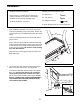
8. Tighten two #8 x 3/4" Screws (86) into the Console Base
(109) and the Upright (93). Do not overtighten the
Screws.
Identify the Left and Right Handrail Assemblies (112,
113). Hold the Right Handrail Assembly (113) near
the Upright (93). Insert the pulse wire from the Right
Handrail Assembly through the hole in the Console Base
(109) and out of the top of the Upright.
Apply three drops of the included thread adhesive to the
threaded ends of two 3/8" x 5 1/2" Screws (50). Then,
attach the Right Handrail Assembly (113) to the Upright
(93) with the two Screws and two 3/8" Washers (134).
Start both Screws, and then tighten them. Note:
Torque the Screws to 340 in-lbs.
Attach the Left Handrail Assembly (112) as described
above.
50
50
86
86
93
109
Wire
Wire
112
113
8
Console
Assembly
134
134
110
110
91
110