
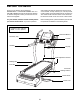
Owner's Manual


8
• Assembly requires two persons.
• Place all parts in a cleared area and remove the
packing materials. Do not dispose of the packing
materialsuntilyounishallassemblysteps.
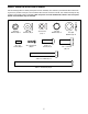
• To identify small parts, see page 7.
• Assembly requires the following tools:
one 3/8" hex key
one 7/32" hex key
one Phillips screwdriver
To avoid damaging parts, do not use power tools.
ASSEMBLY
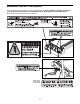
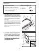
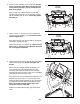
1. Place the Base Frame (56) on two pieces of wood (A)
found in the packaging of the incline trainer. Position the
wood on each side of the Base Frame behind the feet as
shown.
Hold the Upright (93) near the front of the Base Frame
(56) as shown.
As you insert the Upright (93) into the Base Frame (56),
insert the Frame Wire Harness (129) through the bracket
on the right side of the Upright and into the access hole
in the front of the Upright. Be careful to avoid pinching
the Frame Wire Harness.
Align the holes in the Upright (93) with the holes in the
Base Frame (56).
93
56
A
1
Hole
129
2
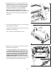
2. Locate the Frame Wire Harness (129) and the Upright
Wire (116) in the access hole in the Upright (93).
Connect the Frame Wire Harness (129) to the Upright
Wire (116). See the inset drawing. The connectors
should slide together easily and snap into place. If
they do not, turn one connector and try again. IF YOU
DO NOT CONNECT THE CONNECTORS PROPERLY,
THE CONSOLE MAY BECOME DAMAGED WHEN
YOU TURN ON THE POWER.
129
116
93
129
116