
Owner's Manual


7
A
ssembly requires two persons
.
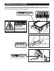
Set the INCLINE TRAINER in a cleared area and remove all packing materials.
Do not dispose of the packing materials until assembly is completed. Assembly can be completed using a 3/8”
hex key, 7/32” hex key and a phillips screwdriver.
For help identifying assembly hardware, see the drawings below. Note: If a part is not found in the part bags,
c
heck to see if the part has been preattached. To avoid damaging plastic parts, do not use power tools for
assembly.
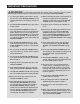
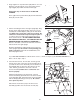
1. Place the Uprights (93) near the front of the Base Frame
(56) as shown.
Locate the wire in the Base Frame (56) and the wire in
the right Upright (93). Plug both wires into one of the
Wire Adapters (130) as shown in the inset drawing.
Make sure to insert the connectors properly; the
connectors should slide easily and snap into place. If
a connector does not slide easily and snap into place,
turn it and then insert it. IF THE CONNECTORS ARE
NOT INSERTED PROPERLY, THE CONSOLE MAY BE
DAMAGED WHEN THE POWER IS TURNED ON.
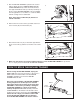
Next, slide the Uprights (93) onto the Base Frame (56),
and align the holes in the Uprights with the holes in the
Base Frame. Be careful to avoid pinching the wires.
Finger tighten two Side Base Bolts (95) through the
bracket near the right Upright and into the Base Frame;
do not tighten the Side Base Bolts yet.
Repeat this step on the left side of the INCLINE
TRAINER. Note: There are no wires on the left side.
93
56
95
Wires
1
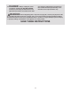
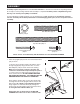
Console Plate Screw
(94)–4*
Display Mounting Screw
(114)–5*
*These Screws are included only with the Workout TV console INCLINE TRAINER.
1/2” Star
Washer (124)–4
Side Base Bolt (95)–4
Top Base Bolt (96)–4
ASSEMBLY
130