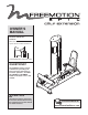
Visit our website at www.proform.com OWNER’S MANUAL Model No. GZFI8136.2 Serial No. Write the serial number in the space above for future reference. new products, prizes, fitness tips, and much more! Visit our website at www.healthrider.com new products, prizes, fitness tips, and much more! Serial Number Decal (inside tower) Visit our website at QUESTIONS? At FreeMotion Fitness, we are committed to providing complete customer satisfaction.
TABLE OF CONTENTS IMPORTANT PRECAUTIONS . . . . . . . . . . . . . . . . . . . . . . . . . . . . . . . . . . . . . . . . . . . . . . . . . . . . . . . . . . . . . . . . 3 WARNING DECAL PLACEMENT . . . . . . . . . . . . . . . . . . . . . . . . . . . . . . . . . . . . . . . . . . . . . . . . . . . . . . . . . . . . . .4 BEFORE YOU BEGIN . . . . . . . . . . . . . . . . . . . . . . . . . . . . . . . . . . . . . . . . . . . . . . . . . . . . . . . . . . . . . . . . . . . . . . 5 ADJUSTMENT . . . . . . . . . . . .
IMPORTANT PRECAUTIONS WARNING: To reduce the risk of serious injury, read all important precautions and instructions in this manual and all warnings on the strength equipment before using the strength equipment. FreeMotion Fitness assumes no responsibility for personal injury or property damage sustained by or through the use of this product. 1. Before beginning this or any exercise program, consult your physician.
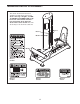
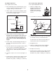
WARNING DECAL PLACEMENT The decals shown below have been applied in the indicated locations. If a decal is missing or illegible, see HOW TO CONTACT CUSTOMER CARE on the back cover of this manual and order a free replacement decal. Apply the decal in the location shown. Note: The decals may not be shown at actual size.
BEFORE YOU BEGIN after reading this manual, see HOW TO CONTACT CUSTOMER CARE on the back cover of this manual. To help us assist you, please note the product model number and serial number before calling. The model number and the location of the serial number decal are shown on the front cover of this manual. Thank you for selecting the FREEMOTION® EPIC™ CALF EXTENSION strength equipment.
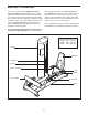
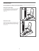
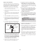
ADJUSTMENT This section explains how to adjust the strength equipment. Make sure all parts are properly tightened each time the strength equipment is used. Replace any worn parts immediately. ADJUSTING THE RESISTANCE To change the amount of resistance for your workout, insert the weight pin into the desired weight. Make sure that the weight pin is fully inserted into the weight stack. Weight Pin Weight Stack ADJUSTING THE SEAT Squeeze the release handle to disengage the release pin (not shown).
MAINTENANCE AND TROUBLESHOOTING For optimal performance of the strength equipment and to reduce the chances of injury to users, you must perform preventive maintenance on a regular basis. Instruct all personnel to perform the procedures described in this section. Personnel must also record and report any accidents. To maintain the strength equipment’s warranty, use only FREEMOTION EPIC parts for repair or replacement.
Cable Traps Check the cable traps to ensure that they are not rubbing against the cables and that they are holding the cables in the grooves of the pulleys. If a cable trap is not correctly aligned, loosen the bolt slightly, readjust the cable trap as necessary, and then retighten the bolt. difficult to insert the weight pin into the weights. If there is not enough tension on the cable, the top weight will not be lifted immediately when the repetition is begun.
Top Weight Adjustment Tools required: 5/32” hex key Press Frame Pulley Adjustment Tools required: Adjustable wrench 1. If the cable needs to be shortened 3/4 in. (2 cm) or more, follow the instructions in steps 1 and 2 on page 8; then, go to step 2 below. 1. Lift the top weight off the weight stack and insert the weight pin into the next weight and the sixth hole from the top of the weight selector. 2. Lift the coupler cover from the top weight coupler.
WEIGHT STACK SERVICING Servicing the weight stack involves replacing the two guide bushings and the weight insert in the top weight. To order these parts, see HOW TO CONTACT CUSTOMER CARE on the back cover of this manual. 1. Remove the wingnuts under the tower cap and remove the tower cap from the tower. 2. Remove the nuts and washers from the tops of the weight guides. 3. Lift the coupler cover on the end of the cable, and loosen the four set screws—this will release the cable. 4.
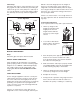
CABLE DIAGRAM The cable diagram shows the proper route of the cable. Use the diagram to make sure that the cable and the cable traps have been assembled correctly. If the cable has not been correctly routed, the strength equipment will not function properly and damage may occur. The numbers show the correct route of the cable. Make sure that the cable traps do not touch or bind the cable. 6 7 49 Do not tighten the Set Screws (49) more than 150 inch/pounds (17 Newton-meters).
NOTES 12
PART LIST—Model No. GZFI8136.2 R0108A If replacement parts are needed, or if parts are missing or damaged, see HOW TO CONTACT CUSTOMER CARE on the back cover of this manual. Key No. Qty. 1 2 3 4 5 6 7 8 9 10 11 12 13 14 15 16 17 18 19 20 21 22 23 24 25 26 27 28 29 30 31 32 33 34 35 36 37 38 39 40 41 42 43 44 1 1 1 1 1 1 1 1 1 1 1 3 1 1 1 1 19 1 2 2 4 1 1 1 2 2 1 1 2 2 1 2 3 4 3 6 1 2 1 1 2 5 2 1 Description Key No. Qty.
EXPLODED DRAWING A—Model No. GZFI8136.
EXPLODED DRAWING B—Model No. GZFI8136.
HOW TO CONTACT CUSTOMER CARE If you have questions after reading this manual, or if you require assistance, please contact Customer Care at the address and phone number listed below. Please be prepared to give the following information: • the MODEL NUMBER of the product (GZFI8136.