www.iconfitness.com Model No. SFEL16112.1 Serial No. Write the serial number in the space above for reference. Serial Number Decal ACTIVATE YOUR WARRANTY To register your product and activate your warranty today, go to www.iconservice.com/ registration. CUSTOMER CARE For service at any time, go to www.iconservice.com. Or call 1-800-999-3756 Mon.–Fri. 6 a.m.–6 p.m. MT Sat. 8 a.m.–4 p.m. MT Please do not contact the store.
TABLE OF CONTENTS WARNING DECAL PLACEMENT . . . . . . . . . . . . . . . . . . . . . . . . . . . . . . . . . . . . . . . . . . . . . . . . . . . . . . . . . . . . . . . 2 IMPORTANT PRECAUTIONS . . . . . . . . . . . . . . . . . . . . . . . . . . . . . . . . . . . . . . . . . . . . . . . . . . . . . . . . . . . . . . . . . . 3 BEFORE YOU BEGIN. . . . . . . . . . . . . . . . . . . . . . . . . . . . . . . . . . . . . . . . . . . . . . . . . . . . . . . . . . . . . . . . . . . . . . . .
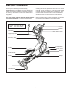
IMPORTANT PRECAUTIONS WARNING: To reduce the risk of burns, fire, electric shock, or injury to persons, read all important precautions and instructions in this manual and all warnings on your elliptical before using your elliptical. ICON assumes no responsibility for personal injury or property damage sustained by or through the use of this product. 1. It is the responsibility of the owner to ensure that all users of the elliptical are adequately informed of all precautions. 11.
STANDARD SERVICE PLANS all 5
BEFORE YOU BEGIN Thank you for selecting the revolutionary FREEMOTION® 515 elliptical. The 515 elliptical provides an impressive selection of features designed to make your workouts at home more effective and enjoyable. reading this manual, please see the front cover of this manual. To help us assist you, note the product model number and serial number before contacting us. The model number and the location of the serial number decal are shown on the front cover of this manual.
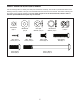
PART IDENTIFICATION CHART Use the drawings below to identify the small parts needed for assembly. The number in parentheses below each drawing is the key number of the part, from the PART LIST near the end of this manual. The number following the key number is the quantity needed for assembly. Note: If a part is not in the hardware kit, check to see if it has been preassembled. Extra parts may be included.
ASSEMBLY • To hire an authorized service technician to assemble this product, call 1-800-445-2480. • To identify small parts, see page 7. • In addition to the included tool(s), assembly requires the following tools: • Assembly requires two persons. • Place all parts in a cleared area and remove the packing materials. Do not dispose of the packing materials until you nish all assembly steps.
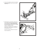
3. Press the Cover Mounts (106) on the underside of the Rear Stabilizer Cover (15) into the Rear Stabilizer (2). 3 15 106 2 4. With the help of a second person, place some of the packing materials (not shown) under the front of the Frame (1). Have the second person hold the Frame to prevent it from tipping while you complete this step. 4 6 105 Attach the Front Stabilizer (6) to the Frame (1) with two M10 x 122mm Screws (104) and two M10 Split Washers (105).
5. Orient the Upright (4) as shown. Have a second person hold the Upright near the Frame (1). 5 Wire Tie See the inset drawing. Locate the wire tie in the lower end of the Upright (4). Tie the wire tie to the Main Wire (110). Then, pull the upper end of the wire tie until the Main Wire is routed through the Upright. 110 4 Tip: To prevent the Main Wire (110) from falling into the Upright (4), secure the Main Wire with the wire tie. 110 Wire Tie 6. Tip: Avoid pinching the Main Wire (110).
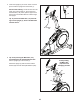
7. Using a plastic bag to keep your fingers clean, apply some of the included grease to the Pivot Axle (35) and to two 16mm Wave Washers (54). 7 Insert the Pivot Axle (35) through the Upright (4) and center it. Tip: It may be helpful to use a rubber mallet. 4 Identify the Right Upper Body Leg (60) and orient it as shown. 35 Grease 46 54 Slide a 16mm Wave Washer (54) and the Right Upper Body Leg (60) onto the right side of the Pivot Axle (35).
9. Untie and discard the wire tie on the Main Wire (110). 9 7 While a second person holds the Console (7) near the Upright (4), connect the wires on the Console to the Main Wire (110), to the Sensor Wires (63), and to the Receiver Extension Wire (111). 63 111 Insert the excess wire into the Upright (4). 110 10. Tip: Avoid pinching the wires. Attach the Console (7) to the Upright (4) with four M4 x 16mm Screws (101).
11. Identify the Right Pedal Arm (58), and orient it as shown. 11 44 Attach the Right Pedal (49) to the Right Pedal Plate (131) on the Right Pedal Arm (58) with four M6 x 12mm Screws (103). 126 49 Repeat this step for the Left Pedal Arm (44) and the Left Pedal (126). 58 131 103 103 12. Orient the Right Pedal Arm (58) as shown. 12 Apply grease to the axle on the Right Pedal Arm (58).
13. Apply a small amount of grease to one of the Pedal Arm Axles (64). 13 Next, slide an M8 Washer (97) and an Axle Spacer (77) onto an M8 x 13mm Screw (82), and tighten the Screw a few turns into the Pedal Arm Axle (64). 46 While a second person holds the front end of the Right Pedal Arm (58) inside the bracket on the Right Upper Body Leg (60), insert the Pedal Arm Axle (64) into both parts.
. Identify the Right Upper Body Arm Front Cover (65) and orient it as shown. 15 Attach the Right Upper Body Arm Front Cover (65) to the Right Upper Body Leg (60) with two M4 x 16mm Screws (101). Identify the Right Upper Body Arm Rear Cover (66) and orient it as shown. 65 Attach the Right Upper Body Arm Rear Cover (66) around the Right Upper Body Leg (60) by pressing it onto the Right Upper Body Arm Front Cover (65). 60 101 Repeat this step on the other side of the elliptical. 66 16.
17. Orient the Shield Cover Cap (118) and the Shield Cover (75) as shown. 17 118 First, press the tabs on the Shield Cover Cap (118) into the Left and Right Shields (73, 74). 73, 74 Then, press the tabs on the Shield Cover (75) into the Left and Right Shields (73, 74). 18. Orient the Rear Console Cover (80) as shown. 75 18 79 Attach the Rear Console Cover (80) to the Upright (4) with two M4 x 16mm Screws (101). Orient the Front Console Cover (79) as shown.
If you purchase the optional chest heart rate monitor (see page 28), follow the additional step below to install the receiver included with the heart rate monitor. 20. Note: If you have already assembled the elliptical, reverse steps 15 and 14. 20 See the inset drawing. Remove the paper from the adhesive pad on the back of the receiver (A). Orient the receiver so that the antenna on the receiver is in a horizontal position parallel to the floor.
HOW TO USE THE ELLIPTICAL HOW TO PLUG IN THE POWER CORD A temporary adapter may be used to connect the power cord to a 2-pole receptacle as shown at the right if a properly grounded outlet is not available. This product must be grounded. If it should malfunction or break down, grounding provides a path of least resistance for electric current to reduce the risk of electric shock. The power cord has a plug with a grounding pin.
HOW TO MOVE THE ELLIPTICAL HOW TO ADJUST THE POSITIONS OF THE PEDALS Due to the size and weight of the elliptical, moving it requires two persons. Stand in front of the elliptical, hold the upright, and place one foot against one of the wheels. Pull on the upright and have a second person lift the handle until the elliptical will roll on the wheels. Carefully move the elliptical to the desired location, and then lower it to the floor. Each pedal can be adjusted to several positions.
HOW TO EXERCISE ON THE ELLIPTICAL To mount the elliptical, hold the handlebars or the upper body arms and step onto the pedal that is in the lower position. Then, step onto the other pedal. Push the pedals until they begin to move with a continuous motion. Note: The pedals can turn in either direction. It is recommended that you turn the pedals in the direction shown by the arrow; however, for variety, you can turn the pedals in the opposite direction.
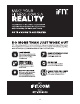
CONSOLE DIAGRAM FEATURES OF THE CONSOLE through an optional iFit module. With the iFit mode, you can download personalized workouts, create your own workouts, track your workout results, race against other iFit users, and access many other features. To purchase an iFit module at any time, go to www. iFit.com or call the telephone number on the front cover of this manual. The advanced console offers an array of features designed to make your workouts more effective and enjoyable.
HOW TO TURN ON THE POWER 3. Change the resistance of the pedals and the incline of the ramp as desired. IMPORTANT: If the elliptical has been exposed to cold temperatures, allow it to warm to room temperature before you turn on the power. If you do not do this, you may damage the console displays or other electrical components. Plug in the power cord (see HOW TO PLUG IN THE POWER CORD on page 18). Next, locate the power switch on the frame near the power cord. Press the power switch to the reset position.
Incline—This display mode will show the incline level of the ramp for a few seconds each time the incline level changes. Press the Home button to return to the default menu (see HOW TO CHANGE CONSOLE SETTINGS on page 29 to set the default menu). If necessary, press the Home button again. Pulse—This display mode will show your heart rate when you use the handgrip heart rate monitor or the optional chest heart rate monitor (see step 5).
When your pulse is detected, a heart symbol in the calorie display will flash each time your heart beats, one or two dashes will appear, and then your heart rate will be shown. For the most accurate heart rate reading, hold the contacts for at least 15 seconds. HOW TO USE AN ONBOARD WORKOUT 1. Begin pedaling or press any button on the console to turn on the console. See HOW TO TURN ON THE POWER on page 22. If the display does not show your heart rate, make sure that your hands are positioned as described.
At the end of each segment of the workout, a series of tones will sound and the next segment of the profile will begin to flash. If a different resistance level, ramp incline level, and/or target rpm is programmed for the next segment, the resistance level, ramp incline level, and/or target rpm will appear in the display for a few seconds to alert you. The resistance of the pedals and the incline level of the ramp will then change.
HOW TO USE A SET-A-GOAL WORKOUT Note: If you manually change the resistance during a calorie goal workout, the length of the workout will adjust automatically to ensure that you meet your calorie goal. 1. Begin pedaling or press any button on the console to turn on the console. See HOW TO TURN ON THE POWER on page 22. Note: The calorie goal is an estimate of the number of calories that you will burn during the workout.
HOW TO USE AN IFIT WORKOUT To re-run a recent iFit workout from your schedule, first press the Track button. Next, press the increase and decrease buttons to select the desired workout. Then, press the Enter button to start the workout. You must have an iFit module to use an iFit workout. To purchase an iFit module at any time, go to www.iFit.com or call the telephone number on the front cover of this manual. To use a set-a-goal workout, press the Set A Goal button (see page 26).
During a competition workout, the Competition tab will show your progress in the race. As you race, the top line in the matrix will show how much of the race you have completed. The other lines will show other competitors. The end of the matrix represents the end of the race.
HOW TO CHANGE CONSOLE SETTINGS If no module is connected, the display will show the words NO IFIT MODULE. If no module is connected, go to step 10. The console features a user mode that allows you to view usage information, select a unit of measurement, and adjust the contrast level of the display. 6. Select an audio setting for the voice of the personal trainer if desired.
FCC INFORMATION This equipment has been tested and found to comply with the limits for a Class B digital device, pursuant to part 15 of the FCC Rules. These limits are designed to provide reasonable protection against harmful interference in a residential installation. This equipment generates, uses, and can radiate radio frequency energy and, if not installed and used in accordance with the instructions, may cause harmful interference to radio communications.
MAINTENANCE AND TROUBLESHOOTING Inspect and tighten all parts of the elliptical regularly. Replace any worn parts immediately. Note: For clarity, the left shield and the left disc ring are shown removed in the drawing below. To clean the elliptical, use a damp cloth and a small amount of mild soap. IMPORTANT: To avoid damage to the console, keep liquids away from the console and keep the console out of direct sunlight. Next, locate the Reed Switch (38).
HOW TO ADJUST THE DRIVE BELT See EXPLODED DRAWING C on page 39. Remove the M4 x 19mm Screws (5) and the M4 x 48mm Screw (107) from the Left and Right Shields (73, 74). Then, remove the Right Shield. If the pedals slip while you are pedaling, even while the resistance is adjusted to the highest level, the drive belt may need to be adjusted. Next, locate and loosen the Idler Screw (89). Tighten the Belt Adjustment Screw (91) until the Drive Belt (113) is tight. Then, retighten the Idler Screw.
EXERCISE GUIDELINES Burning Fat—To burn fat effectively, you must exercise at a low intensity level for a sustained period of time. During the first few minutes of exercise, your body uses carbohydrate calories for energy. Only after the first few minutes of exercise does your body begin to use stored fat calories for energy. If your goal is to burn fat, adjust the intensity of your exercise until your heart rate is near the lowest number in your training zone.
SUGGESTED STRETCHES The correct form for several basic stretches is shown at the right. Move slowly as you stretch; never bounce. 1. Toe Touch Stretch Stand with your knees bent slightly and slowly bend forward from your hips. Allow your back and shoulders to relax as you reach down toward your toes as far as possible. Hold for 15 counts, then relax. Repeat 3 times. Stretches: Hamstrings, back of knees and back. 1 2. Hamstring Stretch Sit with one leg extended.
PART LIST Key No. Qty. 1 2 3 4 5 6 7 8 9 10 11 12 13 14 15 16 17 18 19 20 21 22 23 24 25 26 27 28 29 30 31 32 33 34 35 36 37 38 39 40 41 42 43 44 45 46 47 48 49 50 1 1 1 1 8 1 1 1 1 1 1 1 1 1 1 2 2 1 1 2 4 1 1 1 1 1 4 1 1 4 1 1 2 2 1 2 1 1 1 2 1 1 2 1 1 1 1 1 1 8 Model No. SFEL16112.1 R0113A Description Key No. Qty.
Key No. Qty. 101 102 103 104 105 106 107 108 109 110 111 112 113 114 115 116 117 118 119 120 121 122 123 37 10 8 4 8 3 1 2 2 1 1 1 1 4 1 2 1 1 1 1 6 1 1 Description Key No. Qty.
33 101 121 21 30 104 114 121 3 21 106 15 92 16 105 121 10 33 84 2 121 114 21 101 23 101 30 102 85 120 17 20 90 12 121 84 48 11 21 108 86 26 92 13 38 17 84 14 122 29 22 78 24 50 50 42 101 31 40 27 115 91 88 28 101 102 50 39 101 43 123 82 112 41 25 19 113 43 109 124 125 101 89 93 90 40 1 32 30 6 34 86 124 50 105 18 85 50 20 125 101 90 108 78 30 109 34 104 EXPLODED DRAWING A Model No. SFEL16112.
134 133 129 137 47 76 136 95 103 96 128 103 135 53 44 50 103 95 68 101 57 64 56 77 94 51 100 46 101 97 70 82 82 132 97 101 102 126 62 97 98 56 45 82 97 55 53 82 51 97 57 95 77 98 82 100 67 72 97 57 55 95 57 52 53 56 134 130 127 56 59 50 49 103 135 136 66 100 57 53 95 62 137 131 83 82 101 60 97 57 97 58 77 97 95 87 100 65 57 82 101 61 77 94 57 64 101 69 96 82 97 102 EXPLODED DRAWING B Model No.
101 71 116 7 101 101 5 5 63 107 101 37 101 5 81 8 5 5 80 54 36 73 102 96 4 75 105 99 101 79 101 101 5 5 99 36 105 74 54 117 5 35 118 110 116 102 111 119 39 101 96 63 101 9 101 101 71 EXPLODED DRAWING C Model No. SFEL16112.
ORDERING REPLACEMENT PARTS To order replacement parts, please see the front cover of this manual.