www.iconfitness.com Model No. SFEX04012.2 Serial No. Write the serial number in the space above for reference. Serial Number Decal (under frame) QUESTIONS? If you have questions, or if parts are damaged or missing, DO NOT CONTACT THE STORE; please contact Customer Care. IMPORTANT: Please register this product (see the limited warranty on the back cover of this manual) before contacting Customer Care. CALL TOLL-FREE: 1-800-999-3756 Mon.–Fri. 6 a.m.–6 p.m. MT Sat. 8 a.m.–4 p.m. MT ON THE WEB: www.
TABLE OF CONTENTS WARNING DECAL PLACEMENT . . . . . . . . . . . . . . . . . . . . . . . . . . . . . . . . . . . . . . . . . . . . . . . . . . . . . . . . . . . . . . . 2 IMPORTANT PRECAUTIONS . . . . . . . . . . . . . . . . . . . . . . . . . . . . . . . . . . . . . . . . . . . . . . . . . . . . . . . . . . . . . . . . . . 3 BEFORE YOU BEGIN. . . . . . . . . . . . . . . . . . . . . . . . . . . . . . . . . . . . . . . . . . . . . . . . . . . . . . . . . . . . . . . . . . . . . . . .
IMPORTANT PRECAUTIONS WARNING: To reduce the risk of serious injury, read all important precautions and instructions in this manual and all warnings on your exercise bike before using your exercise bike. ICON assumes no responsibility for personal injury or property damage sustained by or through the use of this product. 1. It is the responsibility of the owner to ensure that all users of the exercise bike are adequately informed of all precautions. 8.
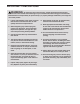
BEFORE YOU BEGIN Thank you for selecting the revolutionary FREEMOTION® 250 U exercise bike. Cycling is one of the most effective exercises for increasing cardiovascular fitness, building endurance, and toning the entire body. The 250 U exercise bike provides an impressive selection of features designed to make your workouts at home more effective and enjoyable. reading this manual, please see the front cover of this manual.
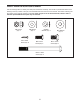
PART IDENTIFICATION CHART Use the drawings below to identify the small parts needed for assembly. The number in parentheses below each drawing is the key number of the part, from the PART LIST near the end of this manual. The number following the key number is the quantity needed for assembly. Note: If a part is not in the hardware kit, check to see if it has been preassembled. Extra parts may be included.
ASSEMBLY • To hire an authorized service technician to assemble this product, call 1-800-445-2480. • In addition to the included tool(s), assembly requires the following tools: • Assembly requires two persons. one Phillips screwdriver • Place all parts in a cleared area and remove the packing materials. Do not dispose of the packing materials until you nish all assembly steps. one adjustable wrench • Left parts are marked “L” or “Left” and right parts are marked “R” or “Right.
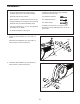
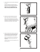
3. Orient the Upright (4) and the Shield Cover (7) as shown. Slide the Shield Cover upward onto the Upright. 3 Have a second person hold the Upright (4) and the Shield Cover (7) near the front of the Frame (1). 4 Locate the wire tie inside the Upright (4). Tie the lower end of the wire tie to the Main Wire Harness (58). Pull the other end of the wire tie upward until the Main Wire Harness (58) is routed through the Upright (4). 7 Wire Tie 58 1 4. Tip: Avoid pinching the wires.
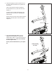
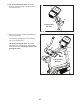
5. Orient the Seat Post (6) as shown, and insert it into the Frame (1). 5 Then, slide the Shield Cover (7) downward and press it onto the Right and Left Shields (10, 11). 6 7 1 10, 11 6. Orient the Knob Shield (9) as shown, and press it onto the Shield Cover (7). 6 Next, tighten the Seat Post Knob (27) into the Frame (1). 7 6 Loosen the Seat Post Knob (27). Then, pull the Seat Post Knob, slide the Seat Post (6) upward or downward to the desired position, and then release the Seat Post Knob.
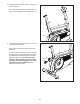
7. Orient the Seat (23) and the Seat Carriage (24) as shown. 7 23 Attach the Seat (23) to the Seat Carriage (24) with four M8 Locknuts (43), four M8 Split Washers (70), and four M8 Washers (64). Note: The Locknuts, Split Washers, and Washers may be preattached to the Seat. 24 64 70 43 8. Remove the Seat Knob (26) from the Seat Bracket (30) inside the Seat Carriage (24). 8 30 Next, set the Seat Carriage (24) on the Seat Post (6).
. Tip: Avoid pinching the wires. Attach the Console (13) to the Upright (4) with four M4 x 16mm Screws (34). 10 13 34 4 Avoid pinching the wires 11. Have a second person hold the Handlebar (5) near the Upright (4). 11 13 Connect the Pulse Wire (61) to the indicated wire on the Console (13). Tip: Avoid pinching the wires. Attach the Handlebar (5) to the Upright (4) with four M8 x 16mm Screws (63); start all four Screws, and then tighten them.
12. Note: For clarity, the Console is not shown in this step. 12 Attach the Front Console Cover (12) to the Upright (4) with two M4 x 16mm Screws (34). 12 4 34 13. Note: For clarity, the Console is not shown in this step. 13 Hold the Rear Console Cover (15) near the Upright (4). Connect the wire on the Rear Console Cover to the Receiver Wire Harness (59). Avoid pinching the wires 12 Tip: Avoid pinching the wires. Press the Rear Console Cover (15) onto the Front Console Cover (12).
15. Identify the Right Pedal (21). 15 Using an adjustable wrench, firmly tighten the Right Pedal (21) clockwise into the Right Crank Arm (19). Tighten the Left Pedal (not shown) counterclockwise into the Left Crank Arm (not shown). Strap To tighten the strap on the Right Pedal (21), pull downward on the end of the strap. To loosen the strap, press the tab and pull upward on the strap. Adjust the strap on the Left Pedal (not shown) in the same way. 16.
EXERCISE BIKE OPERATION HOW TO PLUG IN THE POWER ADAPTER HOW TO ADJUST THE LATERAL POSITION OF THE SEAT IMPORTANT: If the exercise bike has been exposed to cold temperatures, allow it to warm to room temperature before plugging in the power adapter. If you do not do this, you may damage the console displays or other electronic components. To adjust the lateral position of the seat, first loosen the seat knob a few turns.
CONSOLE DIAGRAM FEATURES OF THE CONSOLE The advanced console offers an array of features designed to make your workouts more effective and enjoyable. When you use the manual mode of the console, you can change the resistance of the pedals with the touch of a button. While you exercise, the console will display continuous exercise feedback. You can also measure your heart rate using the handgrip heart rate monitor or an optional chest heart rate monitor. The console offers twenty-two onboard workouts.
HOW TO USE THE MANUAL MODE Distance (Dist.)—This display mode will show the distance that you have pedaled in miles or kilometers. 1. Begin pedaling or press any button on the console to turn on the console. Pulse—This display mode will show your heart rate when you use the handgrip heart rate monitor or an optional chest heart rate monitor (see step 5). When you turn on the console, the display will turn on. The console will then be ready for use. 2. Select the manual mode. Resistance (Resist.
Press the Home button to return to the default menu (see HOW TO CHANGE CONSOLE SETTINGS on page 21 to set the default menu). If necessary, press the Home button again. When your pulse is detected, a heart symbol will flash in the display each time your heart beats, one or two dashes will appear, and then your heart rate will be shown. For the most accurate heart rate reading, hold the contacts for at least 15 seconds.
HOW TO USE AN ONBOARD WORKOUT As you exercise, you will be prompted to keep your pedaling speed near the target speed for the current segment. When an upward-pointing arrow appears in the display, increase your pedaling speed. When a downward-pointing arrow appears, decrease your pedaling speed. When no arrow appears, maintain your current pedaling speed. 1. Begin pedaling or press any button on the console to turn on the console. When you turn on the console, the display will turn on.
HOW TO USE A SET-A-GOAL WORKOUT Note: If you manually change the resistance during a calorie goal workout, the length of the workout will adjust automatically to ensure that you meet your calorie goal. 1. Begin pedaling or press any button on the console to turn on the console. When you turn on the console, the display will turn on. The console will then be ready for use. Note: The calorie goal is an estimate of the number of calories that you will burn during the workout.
HOW TO USE AN IFIT WORKOUT Press the Map button, the Train button, or the Lose Wt. button to download the next workout of that type in your schedule. 1. Begin pedaling or press any button on the console to turn on the console. Press the Compete button to compete in a race that you have previously scheduled. When you turn on the console, the display will turn on. The console will then be ready for use. Press the Track button to re-run a recent iFit workout from your schedule.
6. Follow your progress with the display. HOW TO USE THE SOUND SYSTEM See step 4 on page 15. To play music or audio books through the console sound system while you exercise, plug your audio cable into the jack on the console and into a jack on your MP3 player or CD player; make sure that your audio cable is fully plugged in. The My Trail tab will show a map of the trail you are walking or running or it will show a track and the number of laps you complete.
HOW TO CHANGE CONSOLE SETTINGS If no module is connected, the display will show the words NO IFIT MODULE. If no module is connected, go to step 10. The console features a user mode that allows you to view usage information, select a unit of measurement, and adjust the contrast level of the display. 6. Select an audio setting for the voice of the personal trainer if desired.
FCC INFORMATION This equipment has been tested and found to comply with the limits for a Class B digital device, pursuant to part 15 of the FCC Rules. These limits are designed to provide reasonable protection against harmful interference in a residential installation. This equipment generates, uses, and can radiate radio frequency energy and, if not installed and used in accordance with the instructions, may cause harmful interference to radio communications.
MAINTENANCE AND TROUBLESHOOTING Inspect and properly tighten all parts of the exercise bike regularly. The exercise bike can be cleaned with a soft, damp cloth. To prevent damage to the console, keep liquids away from the console and keep the console out of direct sunlight. Then, remove all of the Screws (not shown) from the Right and Left Shields (10, 11). Carefully pull the tops of the Shields (10, 11) apart, and locate the Reed Switch (57). Loosen, but do not remove, the ST4.2 x 19mm Screw (35).
EXERCISE GUIDELINES Burning Fat—To burn fat effectively, you must exercise at a low intensity level for a sustained period of time. During the first few minutes of exercise, your body uses carbohydrate calories for energy. Only after the first few minutes of exercise does your body begin to use stored fat calories for energy. If your goal is to burn fat, adjust the intensity of your exercise until your heart rate is near the lowest number in your training zone.
SUGGESTED STRETCHES The correct form for several basic stretches is shown at the right. Move slowly as you stretch; never bounce. 1. Toe Touch Stretch Stand with your knees bent slightly and slowly bend forward from your hips. Allow your back and shoulders to relax as you reach down toward your toes as far as possible. Hold for 15 counts, then relax. Repeat 3 times. Stretches: Hamstrings, back of knees and back. 1 2. Hamstring Stretch Sit with one leg extended.
PART LIST Key No. Qty. 1 2 3 4 5 6 7 8 9 10 11 12 13 14 15 16 17 18 19 20 21 22 23 24 25 26 27 28 29 30 31 32 33 34 35 36 1 1 1 1 1 1 1 1 1 1 1 1 1 1 1 1 2 2 1 1 1 1 1 1 2 1 1 1 1 1 4 2 2 26 1 2 Model No. SFEX04012.2 R1012A Description Key No. Qty.
EXPLODED DRAWING 11 34 34 Model No. SFEX04012.
ORDERING REPLACEMENT PARTS To order replacement parts, please see the front cover of this manual.