AT Re TT E ma n ad all NTIO u al b part N s e you for e o in t his r sc p o ot e e ra tin g r Companion Companion FR168-3A2 USERS INSTRUCTION MANUAL
FOREWORD Please read and follow all instructions in this Users Instruction Manual before attempting to operate your Companion Scooter for the first time. If there is anything in this manual that you do not understand, or if you require additional assistance for setting it up, contact your Authorised Freerider Agent. Using your Freerider product safely depends upon your diligence in following the warnings, cautions and instructions in this manual.
PRODUCT DESCRIPTION The three wheeled Companion Scooter supplied has fitted as standard the following features: G Rear-wheel drive via sealed drive axle. G 17 A/H sealed non-maintenance lead-acid batteries. G Automatic charging system. G Off-Board charging facility. G Seat with folding backrest, height adjustment and adjustable width arm-rests. G A multi-positional handlebar for greater comfort.
PURPOSE OF YOUR COMPANION SCOOTER designed for a single occupant who experiences difficulty or discomfort when walking for prolonged periods, but has the use of both legs and the physical, visual and cognitive ability to operate the Scooter safely. Your Companion Scooter is suitable for persons who require independent mobility combined with comfort, manouevreability, reliability and a product that needs a minimal amount of maintenance.
8. Do not reverse your Companion onto uneven inclines or surfaces. Be cautious when traversing slopes. 9. Do not drive your Companion in a confined space unless the speed adjustment dial is set low. 21. Always avoid uneven surfaces. 22. Always consult your physician or a therapist if in doubt about your ability to operate a Scooter. 23. Transport - Do not sit on your Companion while it is in a moving vehicle. Always strap down your Companion then transfer to the vehicle seat. 10.
SAFETY - The advanced speed controller has been designed with extensive self-checking circuits to give you the maximum ‘state-of-the-art’ safety technology. Fully automatic braking gives the driver confidence in any environment. The on/off key can be removed for added security and safety, this disables the electronic drive circuitry, and your Companion cannot therefore be easily driven away by any other person.
3. Armrest Angle Adjustment: (Fig 3). The armrest angle can be adjusted individually to suit your needs. To make adjustments to the armrest angle you will need two 13mm spanners (not provided). Lift the arm upwards, you will note the adjusting bolt. First loosen the locking nut, rotate the bolt in or out until the required angle is found, lower the arm and check the angle for comfort; re-adjust as necessary. Finally tighten the locking nut.
maximum (‘max’) increments. Turn the dial knob anticlockwise to minimum for a very gentle operation, and clockwise towards maximum to increase your speed. NOTE: When attempting to climb obstacles, you will need to set the dial to a high setting. Remember the higher position you set your speed dial to, the faster your Scooter will travel. 2. Horn Buttons: (yellow). Sounds a polite warning signal. 3. On-Off Power Switch: Located at the lower right side of the control console.
Note : Your approved Freerider distributor can modify your vehicle for left-hand forward operation use. FORWARD, REVERSE CONTROL LEVER (Wig wag) Located under the handlebar grips (Fig 9). Your speed for forwards and reverse motion and braking is controlled here. The right thumb lever moves your Companion in a forwards direction and also controls the rate of speed by the proportional amount of pressure applied.
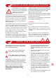
SAFETY INSTRUCTIONS & WARNINGS GENERAL Warning: It is critical that the pressure in the pneumatic tyres is maintained at 30 p.s.i. (210 kpa) at all times. Failure to observe this warning may result in a serious failure of the tyre or wheel, causing serious personal injury and/or damage to your Scooter. Warning: Do not attempt to operate your new Companion Scooter for the first time without completely reading and understanding all of the facts in this Users Instruction Manual.
Warning: When cornering sharply, reduce your speed. When using your Companion at higher speeds, anticipate changes in the road surface. This will greatly reduce the possibility of a tip or fall. To avoid personal injury or property damage, always exercise common sense when cornering. STREET AND ROADWAY DRIVING BRAKING Your Companion Scooter must be driven with due care and compliance with the Road Traffic Acts and conditions of the Highway Code. Always obey all local pedestrian traffic rules.
Warning: Always inflate your tyres from a regulated air source. Over inflation from an unregulated air source could over inflate your tyres resulting in “blow out” or personal injury. It is critically important that pneumatic tyres are inflated to 30 p.s.i. (210 kpa). Do not over inflate your tyres to the maximum inflation pressure of 50 p.s.i. (350 kpa) indicated on the tyre cover, failure to observe this warning could damage your Scooter wheels.
Never remove the anti-tip wheels of your Scooter, they are an important part of your Scooters design. See also Control on an Incline page 15. 8 degrees maximum incline PREVENTING UNINTENDED MOVEMENT Warning: If you anticipate being seated in a stationary position for an extended period of time turn off the power key switch, this will prevent unexpected motion due to inadvertent movement of the direction control (wig-wag) lever. Failure to observe this warning may result in personal injury.
LEARNING TO GET ABOUT Warning: Please take care not to have your thumb on the forward/reverse control lever when you switch ‘on’ your Companion; this will result in your machine going into a fault mode. Switch ‘off’ then ‘on’ again to clear the fault. Warning: If your Companion has been adapted for left hand, forward operation then this procedure will be reversed: i.e. pressing with the left thumb for forward direction and the right thumb for reverse direction.
CONTROL ON AN INCLINE If you must steer in a tight spot, such as entering a doorway or when turning around, stop, turn the handlebars to where you want to go, then apply the power gently. This will make the Companion turn sharply. It will still go gently, and with complete stability. Practice in an open area, until you are proficient. More and more buildings have ramps for wheelchair access. Some have a change of direction in the middle, and good cornering is required.
Most new pavements have wheelchair access ramps at intersections, use these at all times. Plan your route where possible to avoid poor and uneven surfaces. Do not attempt to ride up or down kerbs as you may ground your Scooter and damage it’s construction. CONTROL OVER GRASS & GRAVEL ETC. Care must be taken when attempting to drive over soft surfaces such as those found in parks etc. The surface may look level, but this can be deceiving and hidden dangers may make your Companion become unstable or grounded.
DISMANTLING YOUR COMPANION FOR JOURNEYS AWAY. To enable your Companion Scooter to be carried in a suitable estate or hatchback car (see fig 15), follow these simple instructions for dismantling your scooter. This procedure can be carried out quickly and without tools. Please Note: Your two batteries are supplied in carrying holders. These will be fitted to your batteries by your Freerider Agent.
DISMANTLING PROCEDURE Drive your Companion close to the vehicle into which you are about to load it. You may need some assistance to lift the components once your machine is dismantled. 1. Switch off your scooter. First remove the seat by releasing the ‘black’ locking lever. Rotate the seat 90˚ to the right or left, lift the seat upwards slightly twisting. This will release it from its mounting tube (Fig 1, page 6). 2. Lift the black battery cover positioned to the rear of your foot mat (fig 22).
Your Companion is now dismantled into six basic parts (fig 30). You can now load your Companion Scooter into your car (see fig 15, page 16) Caution: Protect clothing when lifting Scooter parts, some components may have lubricating fluids on their surfaces. Work out the best position to stow each part of your machine, this will vary with different car designs. An old blanket can be used to stop the various parts rubbing against each other.
R E - A S S E M B L I N G Y O U R C O M PA N I O N 4. Lock the two chassis sections together by pushing forward on the seat mounting post, this allows the rear support leg to pivot upwards under spring pressure and the two chassis sections lock together. You will note the locking mechanism knob moves up and down during this operation with an audible “click”. HOW TO RE-ASSEMBLE YOUR COMPANION. Your Companion is very easy to re-assemble once you reach your destination.
B AT T E R I E S & B AT T E R Y C H A R G I N G BATTERY INSTALLATION BATTERY CHARGING Your Companion Scooter is equipped with two maintenance free 12 volt batteries. The batteries are linked together by wiring cables to supply the electronic system with 24 volts of power Your Companion has a lot of power for a small Scooter. Keeping it working to its maximum potential means that its two batteries must be maintained with full power.
5. When the batteries are 90% recharged, the ‘90% Charged’ indicator light will illuminate (second yellow light). The charging cycle is complete when the green ‘Charge Complete Light’ illuminates. The four coloured lights on the front panel of the Charger provide charging status indication as shown below. It is not necessary to disconnect your Charger immediately the ‘Charge Complete’ light illuminates.
CHARGER FAULT INDICATIONS SYMPTOMS Red mains on indicator will not illuminate when charger supply switched on. POSSIBLE CAUSE SUGGESTED ACTION Mains plug fuse 5A failed. Charger T1A fuse located inside of case failed. Charger supply not switched on. Mains supply not present. Charger fault. Replace fuse with identical type. Replace fuse with identical type. Switch supply on. Check supply present with another appliance. Return Charger for repair. Indicator lights No.
CHARGING YOUR BATTERIES AWAY FROM YOUR SCOOTER called the ‘Bulk Charging’ stage. As the battery voltage approaches 90% of the full charge capacity, the Charger reduces its output for the final stage of the re-charge cycle. The time taken from switch-on to the end of the bulk charging will vary, depending on the amount that the batteries have been used, or in time their age.
3. Give your batteries another full charge and run the vehicle again. The batteries will now perform to over 90% of their full potential. 3. Storing batteries : Batteries should always be stored fully charged. Check once a month and recharge fully if needed. Sealed batteries can hold their charge for approx. 6 months. If they are left connected on the Scooter, remember key switches, meters and electronic circuits can drain the batteries rapidly.
CHARGER MAINS PLUG PLUG WIRING INSTRUCTIONS Your Charger’s main input cord is already fitted with a moulded plug incorporating a fuse, the value of which is indicated on the pin face of the plug. Should the fuse need to be replaced, an ASTA approved BS1362 fuse must be used of the same rating. If the plug supplied is not suitable for your socket outlet, it should be cut off and destroyed*. The end of the flexible cord should be suitably prepared and the correct plug fitted.
DRIVE TRANSMISSION LUBRICATION This unit is factory filled and will not normally need additional lubrication. Note: Your Freerider Companion transmission is filled with a special lubricant. Do not attempt to force grease into the transmission as this will contaminate the original lubrication and will invalidate your guarantee. Caution: Take care when lifting the transmission, keep well away from clothing. It is normal to find a light film of lubrication around this part.
result in an uncomfortable ride. Underinflation will result in poor battery and motor performance. Do not exceed the maximum pressures marked on the side wall of the tyre, this could damage the tyre or wheel rim. 4. Slide the wheel from the mounting axle. Rear wheels are fitted to the drive axle via a hub which locates onto a key. These wheels fit tight onto the axle and may need some pressure from a bearing puller onto the wheel hub to release them from the axles.
• Main control box electrical connections RECOMMENDED SERVICE INTERVALS • Main wiring loom for damage DAILY Check the following: • Operation of motor brakes (see page 11 & 27) • All steering components • Clean chassis and repaint any exposed parts • Operation of driving brake (see page 9 & 27) • Lubricate on/off power key barrel • Operation of seat lock (see page 6) • Replace any damaged axle seals • Tyre condition (see page 27 & 28) • Cycle test charger for full operation function • Front basket
2. With a 10mm spanner (not supplied) loosen the locking nut positioned on the opposite side to the black locking lever. (Fig 39, page 29) RECOMMENDED AREAS FOR ADJUSTMENT STEERING COLUMN ADJUSTMENT The steering column locking system works on a ‘cam’ principle to lock the column in the desired driving position (see Fig 7 page 8). 3. Next to the locking nut is a chrome threaded ‘clamping nut’ this has a slightly tapered shape. Turn this clamping nut clockwise approximately a quarter of a turn.
IMPORTANT SPEED CONTROLLER INFORMATION observing the number of flashes emitted from the ‘green’ status light on your control console (fig 8-4, page 8). GENERAL DESCRIPTION If your Companion Scooter fails to operate and the green status light is not illuminated, first check the points aforementioned under ‘FAULT FINDING’. The speed controller system incorporates a sophisticated micro-processor design (Fig 42). It is located under the rear cover of your Companion.
STATUS FAULT CODES FLASH CODE (No. of flashes) 1 Flash FAULT DISPLAYED BY PROGRAMMER Battery needs recharging FREERIDER SCOOTER CONDITION Driving still possible COMMENT The battery voltage has dropped below 23.3 volts in neutral. Recharge the batteries soon. 2 Flashes Battery voltage too low Drive inhibited The battery voltage at Controller has dropped to 16.5 volts. Check the battery condition and the connections.
TECHNICAL SPECIFICATION Model Code: FR168-3A2 Companion Cms Ins Total Length 97 38 Maximum width over wheels 53 20.75 manufacturing tolerances.. Note : Your batteries will require a period of “running in” before they will reach their optimum capacity. Up to 20 charge, discharge cycles can be expected before full range is experienced. See also the battery charging section of this manual. Turning Diameter (between walls) 177 69.5 Tyre Size: Front 200x 50, Rear 2.80/2.
37-46cm 75-84cm 16cm 32cm SIZE SPECIFICATION 5.
CIRCUIT DIAGRAMS CIRCUIT DIAGRAM BATTERY WIRING DIAGRAM 12v 12v RED RED BLACK BLACK CONNECTORS BLACK CONNECTORS BLACK CIRCUIT BREAKER BLACK RED RED BLACK RED 35
ADVISORY SAFETY NOTICE susceptible to interference from radio wave sources. Note: There is no easy way to evaluate their effect on the overall immunity of your powered Scooter. Warning: Radio wave sources may affect Scooter control. Your powered Scooter is designed to operate in appropriate environments, however radio wave sources such as radio or TV broadcasting stations, amateur (Ham) radio transmitters, two-way radios and cellular portable telephones can affect powered motorised Scooters. 5.
OPTIONAL ACCESSORIES For information regarding these optional accessories please contact your Authorised Freerider Agent. STICK/UMBRELLA HOLDER REAR BASKET Provides easily accessible additional carrying capacity for shopping. Basket maximum load 4kg (9lbs) Ideal way to carry your walking aids FRONT BASKET BAG COMBINED BASKET STICK HOLDER Combining the usefulness of the rear basket and the stick/crutch holder. Complete with carry strap. Ideal for storing your handbag away from prying eyes.
GUARANTEE TERMS BATTERIES: Batteries carry a limited 12 month guarantee from the original manufacturer which is subject to a stringent wear and tear clause. Any battery faults due to a defect in the original manufacture will normally become obvious within the first two months of use. (See batteries and battery charging section of this manual).
SERVICE HISTORY This section is designed to assist you in keeping a record of any service and repairs to your Freerider Scooter. service agent will also benefit from a documented record and this book should accompany the Scooter when service or repair work is carried out. Should you decide to sell or exchange your Scooter in the future this will prove most helpful to you. Your The service agent will complete this section and return the book to you.
YOUR LOCAL DEALER Freerider (UK) Limited Earlstrees Court, Earlstrees Road Industrial Estate Corby, Northants NN17 4AX United Kingdom Tel +44 (0)1536 443888 Fax +44 (0)1536 443999 Email: info@freerider.co.uk www.freerider.co.uk Registered in England No. 3370389. Registered office as above. Freerider has a policy of continual improvement. We reserve the right to change specification without prior notice.