
Operation Manual


DISMANTLING PROCEDURE
Drive your Companion close to the vehicle into which you
are about to load it. You may need some assistance to lift
the components once your machine is dismantled.
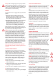
1. Switch off your scooter. First remove the seat by
releasing the ‘black’ locking lever. Rotate the seat 90˚
to the right or left, lift the seat upwards slightly
twisting. This will release it from its mounting tube
(Fig 1, page 6).
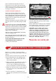
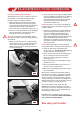
2. Lift the black battery cover positioned to the rear of
your foot mat (fig 22). This is located by four lugs top
and bottom which clip into the plastic body panels.
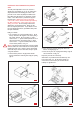
3. Battery Plugs: Disconnect the two
‘
black’ shrouded
battery plugs by pressing the side latch and gently
pulling apart. These plugs are polarised and can only be
fitted together one way. Do not force together when re-
assembling (Fig 23).
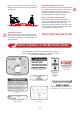
4. Carefully lift up each battery pack with the black strap
provided. Use two hands for this operation, one on the
strap and one to steady the battery (Fig 24).
Note: Make certain that the battery carry pack is fastened
tightly prior to lifting the battery. Place the batteries on a
firm and safe surface. Your batteries are sealed and cannot
spill if tipped over. Always carry the batteries upright.
Warning: Do not place metal objects over open battery
terminals. BEW
ARE of short circuits. Make certain the
terminals are covered by the red and black plastic protectors
at all times.
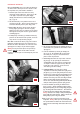
5. Lift the front wire basket from the mounting bracket on
the handlebar cover, you will note this mounts on three
clips (Fig 25).
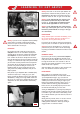
6. Lower the handlebars by releasing the locking lever
(Fig 7, page 8). The handlebar will rest on the floor
mat. Note place a soft piece of material under the
painted console for protection.
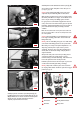
7. Electric Plugs: Disconnect the 6 pin ‘white’ connector
(Fig 26, page 19) by squeezing the small latch and
carefully pulling apart. This connector is polarised and
can only be re-connected together one way. Note the
locating lugs on the connector, do not force these
connectors together when refitting.
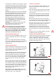
8. Locking Mechanism : The front and rear chassis
components are locked into position with a spring loaded
pin (fig 27, page 19). The spring loaded pin locates into a
hole in the rear of the front chassis unit preventing the two
chassis components from lifting apart during driving. To
unlock the two chassis parts rotate the locking mechanism
knob in an anti-clockwise direction indicated by the “
loosen’ arrow. Turn the knob approximately four full turns
until you can lift it upwards against the spring pressure.
9. Lower the handlebars by releasing the handle bar lock
(see fig 7 page 8). with the handlebars positioned in the
straight ahead position, place the steering locking pin (fig 28,
page 19) through the front location hole. The handle bars
are now prevented from swinging during transportation.
Warning: You must never attempt to drive your Companion
Scooter with the steering pin fitted. Failure to observe this
warning will put you in a dangerous situation.
10.You are now ready to separate the two halves of your
Companion. Warning: Before you carry out this operation,
have you remembered to unfasten the electrical connectors?
Failure to observe this warning could result in unnecessary
damage.
18
FIG 25
FIG 22
FIG 23
FIG 24