
User's Manual


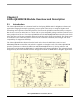
Table Of Contents
- About This Book
- Chapter 1 Safety Information
- Chapter 2 1320x-QE128EVB Module Overview and Description
- Chapter 3 System Overview and Functional Block Descriptions
- Chapter 4 Interface Locations and Pinouts
- Chapter 5 Schematic and Bill of Material

1320x-QE128EVB Module Overview and Description
1320x-QE128EVB Reference Manual, Rev. 0.0
2-2 Freescale Semiconductor
2.2 Features
The 1320x-QE128EVB provides the following features:
• Uses MC9S08QE128 MCU Daughter card - supports the 9S08 based version of the QE128
• Full IEEE 802.15.4 compliant wireless node; ZigBee capable with Freescale’s BeeStack software
stack
• Based on Freescale’s MC13202 transceiver in RF single-port mode
— Printed F-antenna
— Typical RX sensitivity of -92 dBm at 1.0% Packet Error Rate
— Typical 0 dBm up to 3.6 dBm Maximum Output Power
• Based on Freescale’s MC9S08QE128 Microcontroller Unit
— 50 MHz 8-bit 9S08 CPU core / 25 MHz bus speed
— 128 KB flash memory
— Up to 8 KB RAM
— Single-wire background debug interface
— Device available in 64-pin and 80-pin LQFP packages (evaluation board daughter card uses
80-pin device)
• USB interface is bus-powered and full-speed compatible to the USB 2.0 and 1.1 specifications
• Alternate RS-232/UART (DB-9) serial communication port provided
• User interface switches and LEDs
— 4 pushbuttons for application purposes
— 4 processor controlled red LEDs for application purposes
• Supports a 2x16 Character LCD
• Provides an external 1Mbit serial I2C EEPROM
• Audio Resonator
• Uses standard QE128 BDM Development Port
• Supported by Beekit software development environment
• System clock options
— MCU source derived standard from transceiver CLKO (MC13202 transceiver requires 16 MHz
crystal)
— Optional 32.768 kHz crystal oscillator for accurate real-time delays and low Power Modes
• Power management circuit with on-board regulation for multiple power sources
— Can be powered from USB interface, DC power jack or two AA batteries
— On/Off power switch
— Power-on green LED
• MCU & Transceiver RESET via ON/OFF switch (MCU does not support use of a hardware reset
pin when used with the MC13202 transceiver)
• 16-pin and 10-pin user headers for selected General Purpose Input Output signals (GPIO) and data
interfaces