
Integrated Microcontroller Reference Manual

Clock Module
MCF52211 ColdFire® Integrated Microcontroller Reference Manual, Rev. 2
6-16 Freescale Semiconductor
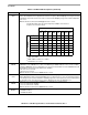
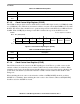
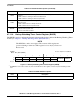
6.7.1.10 Backup Watchdog Timer Control Register (BWCR)
The BWCR is used to configure the interaction between the clock module and the Backup Watchdog Timer
module (see Chapter 7, “Backup Watchdog Timer (BWT) Module”).
NOTE
The BWCR is a write-once register. The contents of this register are
preserved during a warm reset. This register is reset only by a Power-on
Reset event.
2
REFS
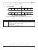
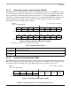
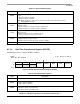
Reference Source bit. This bit configures the RTC oscillator for operation with an external crystal or external
oscillator.
0 RTC oscillator is running in external oscillator mode.
1 RTC oscillator is running in external crystal mode.
1
LPEN
Low-Power Enable bit. This bit configures the RTC oscillator to run in low-power mode when using an
external crystal.
0 RTC oscillator runs in normal-power mode.
1 RTC oscillator runs in low-power mode.
0
RTCSEL
RTC source selection bit. This bit configures the source of the RTC clock.
0 Source is the system clock.
1 Source is the RTC oscillator.
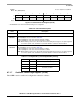
IPSBAR
Offset: 0x12_0013 (BWCR)
Access: Supervisor read/write
76543210
R — — — — ——
BWDSTOP BWDSEL
W
Reset
1
:
1
The BWCR is reset to these values only after a Power-On Reset. The register contents are preserved during a warm
reset.
00000000
Figure 6-11. Backup Watchdog Timer Control Register (BWCR)
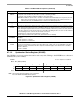
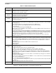
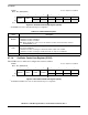
Table 6-15. BWCR Field Descriptions
Field Description
7–2 Reserved, should be cleared.
Table 6-14. RTCCR Field Descriptions (continued)
Field Description