
Integrated Microcontroller Reference Manual

General Purpose Timer Module (GPT)
MCF52211 ColdFire® Integrated Microcontroller Reference Manual, Rev. 2
Freescale Semiconductor 21-15
NOTE
When the fast flag clear all enable bit (GPTSCR1[TFFCA]) is set, any
access to the pulse accumulator counter registers clears all the flags in
GPTPAFLG.
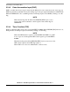
21.6.17 Pulse Accumulator Counter Register (GPTPACNT)
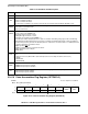
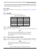
Table 21-19. GPTPAFLG Field Descriptions
Field Description
7–2 Reserved, should be cleared.
1
PAOVF
Pulse accumulator overflow flag. Set when the 16-bit pulse accumulator rolls over from 0xFFFF to 0x0000. If the
GPTPACTL[PAOVI] bit is also set, PAOVF generates an interrupt request. Clear PAOVF by writing a 1 to it. This bit
is read anytime, write anytime. (Writing 1 clears the flag; writing 0 has no effect.)
1 Pulse accumulator overflow
0 No pulse accumulator overflow
0
PAI F
Pulse accumulator input flag. Set when the selected edge is detected at the PAI pin. In event counter mode, the event
edge sets PAIF. In gated time accumulation mode, the trailing edge of the gate signal at the PAI pin sets PAIF. If the
PAI bit in GPTPACTL is also set, PAIF generates an interrupt request. Clear PAIF by writing a 1 to it.
1 Active PAI input
0 No active PAI input
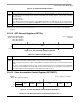
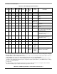
IPSBAR
Offset:
0x1A_001A (GPTPACNT)
Access: Supervisor
read/write
15 14 13 12 11 10 9 8 7 6 5 4 3 2 1 0
R
PAC NT
W
Reset0000000000000 0 0 0
Figure 21-19. Pulse Accumulator Counter Register (GPTPACNT)
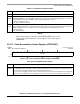
Table 21-20. GPTPACR Field Descriptions
Field Description
15–0
PACNT
Contains the number of active input edges on the PAI pin since the last reset.
Note: Reading the pulse accumulator counter registers immediately after an active edge on the PAI pin may miss the
last count because the input first has to be synchronized with the bus clock.
To ensure coherent reading of the PA counter, such that the counter does not increment between back-to-back 8-bit
reads, it is recommended that only word (16-bit) accesses be used. These bits are read anytime, write anytime.