
Integrated Microcontroller Reference Manual


Pulse-Width Modulation (PWM) Module
MCF52211 ColdFire® Integrated Microcontroller Reference Manual, Rev. 2
27-16 Freescale Semiconductor
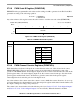
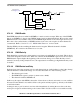
Figure 27-15. PWM Timer Channel Block Diagram
27.3.2.1 PWM Enable
Each PWM channel has an enable bit (PWMEn) to start its waveform output. When any of the PWMEn
bits are set (PWMEn=1), the associated PWM output signal is enabled immediately. However, the actual
PWM waveform is not available on the associated PWM output until its clock source begins its next cycle;
this is due to the synchronization of PWMEn and the clock source. An exception is when channels are
concatenated. Refer to Section 27.3.2.7, “PWM 16-Bit Functions” for more detail.
The first PWM cycle after enabling the channel can be irregular. When the channel is disabled
(PWMEn=0), the counter for the channel does not count.
27.3.2.2 PWM Polarity
Each channel has a polarity bit to allow starting a waveform cycle with a high or low signal. This is shown
on the block diagram as a mux select. When one of the bits in the PWMPOL register is set, the associated
PWM channel output is high at the beginning of the waveform, then goes low when the duty count is
reached. Conversely, if the polarity bit is zero, the output starts low and then goes high when the duty count
is reached.
27.3.2.3 PWM Period and Duty
Dedicated period and duty registers exist for each channel and are double buffered so that if they change
while the channel is enabled, the change does not take effect until one of the following occurs:
• The effective period ends
• The PWMCNTn register is written (counter resets to 0x00)
• The channel is disabled, PWMEn =0
In this way, the output of the PWM is always the old waveform or the new waveform, not some variation
in between. If the channel is not enabled, writes to the period and duty registers go directly to the latches
as well as the buffer.
A change in duty or period can be forced into effect immediately by writing the new value to the duty
and/or period registers and then writing to the counter. This forces the counter to reset and the new duty
PWMCNTn
PWMDTYn
PWMPERn
Up/Down
Reset
PWMCAE = 1
PWMCAE = 0
Clock Source
From Figure 27-14
PPOLn
0
1
PWMOUTn
PWMEn