
Integrated Microcontroller Reference Manual

Pulse-Width Modulation (PWM) Module
MCF52211 ColdFire® Integrated Microcontroller Reference Manual, Rev. 2
Freescale Semiconductor 27-19
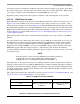
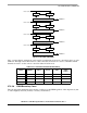
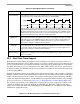
Figure 27-17. PWM Left-Aligned Output Example Waveform
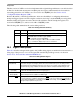
27.3.2.6 Center-Aligned Outputs
For center-aligned output mode selection, set the PWMCAE[CAEn] bit and the corresponding PWM
output is center-aligned.
The 8-bit counter operates as an up/down counter in this mode and is set to up when the counter is equal
to 0x00. The counter compares to two registers, a duty register and a period register, as shown in the block
diagram in Figure 27-15. When the PWM counter matches the duty register, the output flip-flop changes
state, causing the PWM waveform to also change state. A match between the PWM counter and the period
register changes the counter direction from an up-count to a down-count. When the PWM counter
decrements and matches the duty register again, the output flip-flop changes state causing the PWM output
to also change state. When the PWM counter decrements and reaches zero, the counter direction changes
from a down-count back to an up-count, and a load from the double buffer period and duty registers to the
associated registers is performed as described in Figure 27.3.2.3. The counter counts from 0 up to the value
in the period register and then back down to 0. Thus the effective period is PWMPERn × 2.
Changing the PWM output mode from left-aligned output to center-aligned output (or vice versa) while
channels are operating can cause irregularities in the PWM output. It is recommended to program the
output mode before enabling the PWM channel.
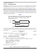
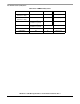
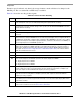
Figure 27-18. PWM Center-Aligned Output Waveform
To calculate the output frequency in center-aligned output mode for a particular channel, take the selected
clock source frequency for the channel (A, B, SA, or SB) and divide it by twice the value in the period
register for that channel.
Eqn. 27-9
The PWMn duty cycle (high time as a percentage of period) is expressed as:
PERIOD = 100ns
DUTY CYCLE = 75%
E = 25ns
PPOLn =0
PPOLn =1
Period = PWMPERn × 2
PWMDTYn
PWMPERn PWMPERn
PWMDTYn
PWMn frequency
Clock (A, B, SA, or SB)
2P× WMPERn
----------------------------------------------------------
=