
Integrated Microcontroller Reference Manual

Debug Module
MCF52211 ColdFire® Integrated Microcontroller Reference Manual, Rev. 2
28-8 Freescale Semiconductor
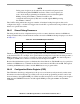
DRc[4:0]: 0x00 (CSR) Access: Supervisor write-only
BDM read/write
31 30 29 28 27 26 25 24 23 22 21 20 19 18 17 16
R BSTAT FOF TRG HALT BKPT HRL 0 0
PCD IPW
W
Reset0000000010010 0 0 0
15 14 13 12 11 10 9 8 7 6 5 4 3 2 1 0
R
MAP TRC EMU DDC UHE BTB
0
NPL IPI SSM
0000
W
Reset0000000000000 0 0 0
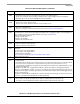
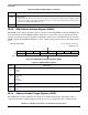
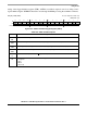
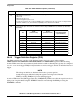
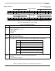
Figure 28-3. Configuration/Status Register (CSR)
Table 28-6. CSR Field Descriptions
Field Description
31–28
BSTAT
Breakpoint Status. Provides read-only status (from the BDM port only) information concerning hardware
breakpoints. BSTAT is cleared by a TDR write or by a CSR read when a level-2 breakpoint is triggered or a level-1
breakpoint is triggered and the level-2 breakpoint is disabled.
0000 No breakpoints enabled
0001 Waiting for level-1 breakpoint
0010 Level-1 breakpoint triggered
0101 Waiting for level-2 breakpoint
0110 Level-2 breakpoint triggered
27
FOF
Fault-on-fault. If FOF is set, a catastrophic halt occurred and forced entry into BDM. FOF is cleared when CSR is
read (from the BDM port only).
26
TRG
Hardware breakpoint trigger. If TRG is set, a hardware breakpoint halted the processor core and forced entry into
BDM. Reset, the debug
GO command or reading CSR (from the BDM port only) clear TRG.
25
HALT
Processor halt. If HALT is set, the processor executed a HALT and forced entry into BDM. Reset, the debug GO
command, or reading CSR (from the BDM port only) clear HALT.
24
BKPT
Breakpoint assert. If BKPT is set, BKPT was asserted, forcing the processor into BDM. Reset, the debug GO
command, or reading CSR (from the BDM port only) clear BKPT.
23–20
HRL
Hardware revision level. Indicates, from the BDM port only, the level of debug module functionality. An emulator
could use this information to identify the level of functionality supported.
0000 Revision A
0001 Revision B
0010 Revision C
0011 Revision D
1001 Revision B+ (This is the value used for this device)
1011 Revision D+
19–18 Reserved, must be cleared.
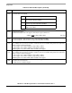
17
PCD
PST/DDATA Disable. Disables the PST/DDATA output signal. PSTCLK is unaffected, it remains under the control
of the SYNCR[DISCLK] bit.
0 Normal operation
1 Disables the generation of the PSTDDATA output signals, and forces these signals to remain quiescent
16
IPW
Inhibit processor writes. Setting IPW inhibits processor-initiated writes to the debug module’s programming model
registers. Only commands from the external development system can modify IPW.