
Integrated Microcontroller Reference Manual

ColdFire Core
MCF52211 ColdFire® Integrated Microcontroller Reference Manual, Rev. 2
3-10 Freescale Semiconductor
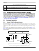
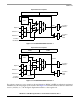
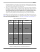
For simple register-to-register instructions, the first stage of the OEP performs the instruction decode and
fetching of the required register operands (OC) from the dual-ported register file, while the actual
instruction execution is performed in the second stage (EX) in one of the execute engines (e.g., ALU,
barrel shifter, divider, EMAC). There are no operand memory accesses associated with this class of
instructions, and the execution time is typically a single machine cycle. See Figure 3-11.
Figure 3-11. V2 OEP Register-to-Register
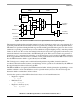
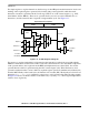
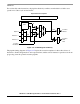
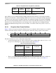
For memory-to-register (embedded-load) instructions, the instruction is effectively staged through the
OEP twice with a basic execution time of three cycles. First, the instruction is decoded and the components
of the operand address (base register from the RGF and displacement) are selected (DS). Second, the
operand effective address is generated using the ALU execute engine (AG). Third, the memory read
operand is fetched from the core bus, while any required register operand is simultaneously fetched (OC)
from the RGF. Finally, in the fourth cycle, the instruction is executed (EX). The heavily-used 32-bit load
instruction (
move.l <mem>y,Rx) is optimized to support a two-cycle execution time. The following example
in Figure 3-12 shows an effective address of the form <ea>y = (d16,Ay), i.e., a 16-bit signed displacement
added to a base register Ay.
Operand Execution Pipeline
DSOC AGEX
Opword
Extension 1
Extension 2
Core Bus
Read Data
Core Bus
Address
Core Bus
Write
Data
new Rx
Rx
Ry
RGF