56F8322/56F8122 Data Sheet Preliminary Technical Data 56F8300 16-bit Hybrid Controllers MC56F8322 Rev. 10.0 10/2004 freescale.
Document Revision History Version History Description of Change Rev 1.0 Pre-Release version, Alpha customers only Rev 2.0 Initial Public Release Rev 3.0 Corrected typo in Table 10-4, Flash Endurance is 10,000 cycles. Addressed additional grammar issues Rev 4.0 Added Package Pins to GPIO table in Section 8. Clarification of TRST usage in this device. Replacing TBD Typical Min with values in Table 10-17. Editing grammar, spelling, consistency of language throughout family.
56F8322/56F8122 General Description Note: Features in italics are NOT available in the 56F8122 device.
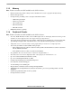
Table of Contents Part 1: Overview . . . . . . . . . . . . . . . . . . . . . . 5 1.1. 1.2. 1.3. 1.4. 1.5. 1.6. 56F8322/56F8122 Features . . . . . . . . . . . . . 5 Device Description . . . . . . . . . . . . . . . . . . . . 7 Award-Winning Development Environment . 8 Architecture Block Diagram . . . . . . . . . . . . . 9 Product Documentation . . . . . . . . . . . . . . . 13 Data Sheet Conventions . . . . . . . . . . . . . . . 13 Part 2: Signal/Connection Descriptions . . 14 2.1. Introduction . . . . . . .
6F8322/56F8122 Features Part 1 Overview 1.1 56F8322/56F8122 Features 1.1.1 • • • • • • • • • • • • • • 1.1.
1.1.3 Memory Note: Features in italics are NOT available in the 56F8122 device. • • • Harvard architecture permits as many as three simultaneous accesses to program and data memory Flash security protection On-chip memory, including a low-cost, high-volume Flash solution — 32KB of Program Flash — 4KB of Program RAM — 8KB of Data Flash — 8KB of Data RAM — 8KB of Boot Flash • 1.1.4 EEPROM emulation capability Peripheral Circuits Note: Features in italics are NOT available in the 56F8122 device.
Device Description 1.1.5 • • • • • • Energy Information Fabricated in high-density CMOS with 5V-tolerant, TTL-compatible digital inputs On-board 3.3V down to 2.6V voltage regulator for powering internal logic and memories On-chip regulators for digital and analog circuitry to lower cost and reduce noise Wait and Stop modes available ADC smart power management Each peripheral can be individually disabled to save power 1.
is programmable to support a continuously variable PWM frequency. Edge-aligned and center-aligned synchronous pulse width control (0% to 100% modulation) is supported. The device is capable of controlling most motor types: ACIM (AC Induction Motors); both BDC and BLDC (Brush and Brushless DC motors); SRM and VRM (Switched and Variable Reluctance Motors); and stepper motors.
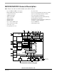
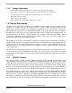
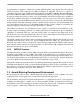
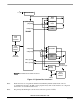
Architecture Block Diagram 1.4 Architecture Block Diagram Note: Features in italics are NOT available in the 56F8122 device and are shaded in the following figures. The 56F8322/56F8122 architecture is shown in Figure 1-1 and Figure 1-2. Figure 1-1 illustrates how the 56800E system buses communicate with internal memories and the IPBus Bridge. Table 1-2 lists the internal buses in the 56800E architecture and provides a brief description of their function.
4 JTAG / EOnCE Boot Flash pdb_m[15:0] pab[20:0] Program Flash cdbw[31:0] Program RAM 56800E CHIP TAP Controller TAP Linking Module xab1[23:0] Data RAM xab2[23:0] Data Flash External JTAG Port cdbr_m[31:0] xdb2_m[15:0] IPBus Bridge To Flash Control Logic Flash Memory Module Not available on the 56F8122 device. IPBus Figure 1-1 System Bus Interfaces Note: Flash memories are encapsulated within the Flash Memory Module (FM).
Architecture Block Diagram To/From IPBus Bridge CLKGEN (OSC/PLL) Interrupt Controller (ROSC) Low-Voltage Interrupt Timer A POR & LVI 4 System POR Quadrature Decoder 0 RESET SIM COP Reset 2 4 FlexCAN 2 COP SPI 1 SCI 1 4 SPI 0 PWMA 3 SYNC Output 2 GPIO A SCI 0 GPIO B GPIO C ch2i 2 Timer C ch2o ADCA 6 TEMP_SENSE Not available on the 56F8122 device.
Table 1-2 Bus Signal Names Name Function Program Memory Interface pdb_m[15:0] Program data bus for instruction word fetches or read operations. cdbw[15:0] Primary core data bus used for program memory writes. (Only these 16 bits of the cdbw[31:0] bus are used for writes to program memory.) pab[20:0] Program memory address bus. Data is returned on pdb_m bus. Primary Data Memory Interface Bus cdbr_m[31:0] Primary core data bus for memory reads. Addressed via xab1 bus.
Product Documentation 1.5 Product Documentation The documents listed in Table 1-3 are required for a complete description and proper design with the 56F8322 and 56F8122 devices. Documentation is available from local Freescale distributors, Freescale semiconductor sales offices, Freescale Literature Distribution Centers, or online at http://www.freescale.com/semiconductors/.
Part 2 Signal/Connection Descriptions 2.1 Introduction The input and output signals of the 56F8322 and 56F8122 devices are organized into functional groups, as detailed in Table 2-1 and as illustrated in Figure 2-1 and Figure 2-2. In Table 2-2, each table row describes the signal or signals present on a pin.
Introduction Power VDD_IO Ground VSS Power Ground VDDA_ADC VSSA_ADC 1 4 4 1 1 1 1 1 56F8322 Other Supply Ports PLL and Clock or GPIO VCAP1 - VCAP2 1 2 1 EXTAL (GPIOC0) XTAL (GPIOC1) 1 1 1 1 2 1 1 1 1 1 3 3 3 1 1 TCK JTAG/ EOnCE Port TMS TDI TDO 1 1 1 PHASEA0 (TA0, GPIOB7) PHASEB0 (TA1, GPIOB6) INDEX0 (TA2, GPIOB5) HOME0 (TA3, GPIOB4) Quadrature Decoder 0 or Quad Timer A or GPIO SCLK0 (GPIOB3) MOSI0 (GPIOB2) MISO0 (RXD1, GPIOB1) SPI0 or SCI1 or GPIO SS0 (TXD1, GPIOB0) PWMA0 -
Power VDD_IO Ground VSS Power Ground VDDA_ADC VSSA_ADC 1 4 4 1 1 1 1 1 56F8122 Other Supply Ports PLL and Clock or GPIO VCAP1 - VCAP2 1 2 1 EXTAL (GPIOC0) XTAL (GPIOC1) 1 1 1 1 2 1 1 1 1 1 3 3 3 1 1 TCK JTAG/ EOnCE Port TMS TDI TDO 1 1 1 TA0 (GPIOB7) TA1 (GPIOB6) TA2 (GPIOB5) Quad Timer A or GPIO TA3 (GPIOB4) SCLK0 (GPIOB3) MOSI0 (GPIOB2) MISO0 (RXD1, GPIOB1) SPI0 or SCI1 or GPIO SS0 (TXD1, GPIOB0) GPIOA0 - 1 SS1 (GPIOA2) MISO1 (GPIOA3) MOSI1 (GPIOA4) SPI1 or GPIO SCLK1 (GP
Signal Pins 2.2 Signal Pins After reset, each pin is configured for its primary function (listed first). In the 56F8122, after reset, each pin must be configured for the desired function. The initialization software will configure each pin for the function listed first for each pin, as shown in Table 2-2. Any alternate functionality must be programmed. Note: Signals in italics are not available in the 56F8122 device.
Table 2-2 Signal and Package Information for the 48-Pin LQFP Signal Name Pin No. Type State During Reset EXTAL 32 Input/ Input Signal Description External Crystal Oscillator Input — This input can be connected to an 8MHz external crystal. If an external clock is used, XTAL must be used as the input and EXTAL connected to VSS. The input clock can be selected to provide the clock directly to the core. This input clock can also be selected as the input clock for the on-chip PLL.
Signal Pins Table 2-2 Signal and Package Information for the 48-Pin LQFP State During Reset Signal Name Pin No. Type PHASEA0 38 Schmitt Input Input Phase A — Quadrature Decoder 0, PHASEA input (TA0) Schmitt Input/ Output Input TA0 — Timer A, Channel 0 (GPIOB7) Schmitt Input/ Output Input Port B GPIO — This GPIO pin can be individually programmed as an input or output pin.
Table 2-2 Signal and Package Information for the 48-Pin LQFP State During Reset Signal Name Pin No. Type INDEX0 36 Schmitt Input Input Index — Quadrature Decoder 0, INDEX input (TA2) Schmitt Input/ Output Input TA2 — Timer A, Channel 2 (GPIOB5) Schmitt Input/ Output Input Port B GPIO — This GPIO pin can be individually programmed as an input or output pin. (SYS_CLK) Output Output Clock Output - can be used to monitor the internal SYS_CLK signal (see Section 6.5.
Signal Pins Table 2-2 Signal and Package Information for the 48-Pin LQFP State During Reset Signal Name Pin No. Type MOSI0 18 Schmitt Input/ Output Tri-stated SPI 0 Master Out/Slave In — This serial data pin is an output from a master device and an input to a slave device. The master device places data on the MOSI line a half-cycle before the clock edge the slave device uses to latch the data.
Table 2-2 Signal and Package Information for the 48-Pin LQFP State During Reset Signal Name Pin No. Type PWMA1 4 Schmitt Output Tri-stated Schmitt Input/ Output Input (GPIOA1) Signal Description PWMA1 — This is one of six PWMA output pins. Port A GPIO - This GPIO pin can be individually programmed as an input or output pin. In the 56F8322, the default state after reset is PWMA1. In the 56F8122, the default state is not one of the functions offered and must be reconfigured.
Signal Pins Table 2-2 Signal and Package Information for the 48-Pin LQFP Signal Name Pin No. Type State During Reset PWMA4 8 Output Tri-stated PWMA4 — This is one of six PWMA output pins. (MOSI1) Schmitt Input/ Output Tri-stated SPI 1 Master Out/Slave In — This serial data pin is an output from a master device and an input to a slave device. The master device places data on the MOSI line a half-cycle before the clock edge the slave device uses to latch the data.
Table 2-2 Signal and Package Information for the 48-Pin LQFP Signal Name Pin No. Type State During Reset VREFP 28 Input/ Output Input/ Output VREFMID 27 VREFN 26 CAN_RX 46 Schmitt Input Input FlexCAN Receive Data — This is the CAN input. This pin has an internal pull-up resistor. Schmitt Input/ Output Input Port C GPIO — This GPIO pin can be individually programmed as an input or output pin.
Signal Pins Table 2-2 Signal and Package Information for the 48-Pin LQFP Signal Name Pin No. Type IRQA 11 Schmitt Input (VPP) RESET 2 Schmitt Input State During Reset Signal Description Input External Interrupt Request A — The IRQA input is an asynchronous external interrupt request during Stop and Wait mode operation. During other operating modes, it is a synchronized external interrupt request which indicates an external device is requesting service.
Part 3 On-Chip Clock Synthesis (OCCS) 3.1 Introduction Refer to the OCCS chapter of the 56F8300 Peripheral User Manual for a full description of the OCCS. The material contained here identifies the specific features of the OCCS design. 3.2 External Clock Operation The system clock can be derived from an external crystal, ceramic resonator or an external system clock signal.
External Clock Operation 3.2.2 Ceramic Resonator (Default) It is also possible to drive the internal oscillator with a ceramic resonator, assuming the overall system design can tolerate the reduced signal integrity. A typical ceramic resonator circuit is shown in Figure 3-2. Refer to the supplier’s recommendations when selecting a ceramic resonator and associated components. The resonator and components should be mounted as near as possible to the EXTAL and XTAL pins.
3.3 Use of On-Chip Relaxation Oscillator An internal relaxtion oscillator can supply the reference frequency when an external frequency source of crystal is not used. During a boot or reset sequence, the relaxation oscillator is enabled by default, and the PRECS bit in the PLLCR word is set to 0. If an external oscillator is connected, the relaxation oscillator can be deselected instead by setting the PRECS bit in the PLLCR to 1.
Registers CLK_MODE MUX Relaxation OSC XTAL MUX PRECS Crystal OSC ZSRC PLLDB FOUT PLL x (1 to 128) PLLCOD ÷2 FOUT/2 Postscaler ÷ (1, 2, 4, 8) FEEDBACK MSTR_OSC Prescaler ÷ (1, 2, 4, 8) FREF PLLCID MUX EXTAL SYS_CLK2 source to the SIM Postscaler CLK Bus Interface & Control Bus Interface LCK Lock Detector Loss of Reference Clock Detector loss of reference clock interrupt Figure 3-4 Internal Clock Operation 3.
Part 4 Memory Map 4.1 Introduction The 56F8322 and 56F8122 devices are 16-bit motor-control chips based on the 56800E core. These parts use a Harvard-style architecture with two independent memory spaces for Data and Program. On-chip RAM and Flash memories are used in both spaces.
Interrupt Vector Table Note: Program RAM is NOT available on the 56F8122 device. Table 4-2 Program Memory Map at Reset Begin/End Address Memory Allocation P: $1F FFFF P: $03 0000 RESERVED P: $02 FFFF P: $02 F800 On-Chip Program RAM 4KB P: $02 F7FF P: $02 1000 RESERVED P: $02 0FFF P: $02 0000 Boot Flash 8KB Cop Reset Address = $02 0002 Boot Location = $02 0000 P: $01 FFFF P: $00 4000 RESERVED P: $00 3FFF P: $00 0000 Internal Program Flash 32KB 4.
Table 4-3 Interrupt Vector Table Contents1 (Continued) Peripheral Vector Number Priority Level Vector Base Address + core 6 1-3 P:$0C core 7 1-3 P:$0E Interrupt Function OnCE Step Counter OnCE Breakpoint Unit 0 Reserved core 9 1-3 P:$12 OnCE Trace Buffer core 10 1-3 P:$14 OnCE Transmit Register Empty core 11 1-3 P:$16 OnCE Receive Register Full core 14 2 P:$1C SW Interrupt 2 core 15 1 P:$1E SW Interrupt 1 core 16 0 P:$20 SW Interrupt 0 core 17 0-2 P:$22 IRQA L
Interrupt Vector Table Table 4-3 Interrupt Vector Table Contents1 (Continued) Peripheral Vector Number Priority Level Vector Base Address + Interrupt Function Reserved TMRC 56 0-2 P:$70 Timer C Channel 0 TMRC 57 0-2 P:$72 Timer C Channel 1 TMRC 58 0-2 P:$74 Timer C Channel 2 TMRC 59 0-2 P:$76 Timer C Channel 3 Reserved TMRA 64 0-2 P:$80 Timer A Channel 0 TMRA 65 0-2 P:$82 Timer A Channel 1 TMRA 66 0-2 P:$84 Timer A Channel 2 TMRA 67 0-2 P:$86 Timer A Channel 3 S
4.4 Data Map Note: Data Flash is NOT available on the 56F8122 device. Table 4-4 Data Memory Map1 Begin/End Address Memory Allocation X:$FF FFFF X:$FF FF00 EOnCE 256 locations allocated X:$FF FEFF X:$01 0000 RESERVED X:$00 FFFF X:$00 F000 On-Chip Peripherals 4096 locations allocated X:$00 EFFF X:$00 2000 RESERVED X:$00 1FFF X:$00 1000 On-Chip Data Flash 8KB X:$00 0FFF X:$00 0000 On-Chip Data RAM 8KB2 1. All addresses are 16-bit Word addresses. 2.
Flash Memory Map Data Memory Program Memory BOOT_FLASH_START + $0FFF FM_BASE + $14 8KB Boot BOOT_FLASH_START = $02_0000 FM_BASE + $00 Reserved Banked Registers Unbanked Registers DATA_FLASH_START + $0FFF 8KB DATA_FLASH_START + $0000 Configure Field FM_PROG_MEM_TOP = $00_3FFF Block 0 Odd Block 0 Even Note: Data Flash is NOT available in the 56F8122 device. ...
4.
Peripheral Memory Mapped Registers The following tables list all of the peripheral registers required to control or access the peripherals. Note: Features in italics are NOT available on the 56F8122 device.
Table 4-8 Quad Timer A Registers Address Map (Continued) (TMRA_BASE = $00 F040) Register Acronym Address Offset Register Description TMRA0_CMPLD2 $9 Comparator Load Register 2 TMRA0_COMSCR $A Comparator Status and Control Register Reserved TMRA1_CMP1 $10 Compare Register 1 TMRA1_CMP2 $11 Compare Register 2 TMRA1_CAP $12 Capture Register TMRA1_LOAD $13 Load Register TMRA1_HOLD $14 Hold Register TMRA1_CNTR $15 Counter Register TMRA1_CTRL $16 Control Register TMRA1_SCR $17 Statu
Peripheral Memory Mapped Registers Table 4-9 Quad Timer C Registers Address Map (TMRC_BASE = $00 F0C0) Register Acronym TMRC0_CMP1 Address Offset $0 Register Description Compare Register 1 TMRC0_CMP2 $1 Compare Register 2 TMRC0_CAP $2 Capture Register TMRC0_LOAD $3 Load Register TMRC0_HOLD $4 Hold Register TMRC0_CNTR $5 Counter Register TMRC0_CTRL $6 Control Register TMRC0_SCR $7 Status and Control Register TMRC0_CMPLD1 $8 Comparator Load Register 1 TMRC0_CMPLD2 $9 Comparator L
Table 4-9 Quad Timer C Registers Address Map (Continued) (TMRC_BASE = $00 F0C0) Register Acronym Address Offset Register Description TMRC3_CMP2 $31 Compare Register 2 TMRC3_CAP $32 Capture Register TMRC3_LOAD $33 Load Register TMRC3_HOLD $34 Hold Register TMRC3_CNTR $35 Counter Register TMRC3_CTRL $36 Control Register TMRC3_SCR $37 Status and Control Register TMRC3_CMPLD1 $38 Comparator Load Register 1 TMRC3_CMPLD2 $39 Comparator Load Register 2 TMRC3_COMSCR $3A Comparator St
Peripheral Memory Mapped Registers Table 4-11 Quadrature Decoder 0 Registers Address Map (DEC0_BASE = $00 F180) Quadrature Decoder is NOT available in the 56F8122 device Register Acronym Address Offset Register Description DEC0_DECCR $0 Decoder Control Register DEC0_FIR $1 Filter Interval Register DEC0_WTR $2 Watchdog Time-out Register DEC0_POSD $3 Position Difference Counter Register DEC0_POSDH $4 Position Difference Counter Hold Register DEC0_REV $5 Revolution Counter Register DEC0_R
Table 4-12 Interrupt Control Registers Address Map (Continued) (ITCN_BASE = $00 F1A0) Register Acronym Address Offset Register Description IRQP 0 $11 IRQ Pending Register 0 IRQP 1 $12 IRQ Pending Register 1 IRQP 2 $13 IRQ Pending Register 2 IRQP 3 $14 IRQ Pending Register 3 IRQP 4 $15 IRQ Pending Register 4 IRQP 5 $16 IRQ Pending Register 5 Reserved ICTL $1D Interrupt Control Register Table 4-13 Analog to Digital Converter Registers Address Map (ADCA_BASE = $00 F200) Register Acronym
Peripheral Memory Mapped Registers Table 4-13 Analog to Digital Converter Registers Address Map (Continued) (ADCA_BASE = $00 F200) Register Acronym ADCA_HLMT 1 Address Offset $1A Register Description High Limit Register 1 ADCA_HLMT 2 $1B High Limit Register 2 ADCA_HLMT 3 $1C High Limit Register 3 ADCA_HLMT 4 $1D High Limit Register 4 ADCA_HLMT 5 $1E High Limit Register 5 ADCA_HLMT 6 $1F High Limit Register 6 ADCA_HLMT 7 $20 High Limit Register 7 ADCA_OFS 0 $21 Offset Register 0 ADCA
Table 4-16 Serial Communication Interface 1 Registers Address Map (SCI1_BASE = $00 F290) Register Acronym Address Offset Register Description SCI1_SCIBR $0 Baud Rate Register SCI1_SCICR $1 Control Register Reserved SCI1_SCISR $3 Status Register SCI1_SCIDR $4 Data Register Table 4-17 Serial Peripheral Interface 0 Registers Address Map (SPI0_BASE = $00 F2A0) Register Acronym SPI0_SPSCR Address Offset Register Description $0 Status and Control Register SPI0_SPDSR $1 Data Size Register SP
Peripheral Memory Mapped Registers Table 4-20 Clock Generation Module Registers Address Map (CLKGEN_BASE = $00 F2D0) Register Acronym Address Offset Register Description PLLCR $0 Control Register PLLDB $1 Divide-By Register PLLSR $2 Status Register Reserved SHUTDOWN $4 Shutdown Register OSCTL $5 Oscillator Control Register Table 4-21 GPIOA Registers Address Map (GPIOA_BASE = $00 F2E0) Register Acronym GPIOA_PUR Address Offset Register Description Reset Value $0 Pull-up Enable Registe
Table 4-23 GPIOC Registers Address Map (GPIOC_BASE = $00F310) Register Acronym Address Offset Register Description Reset Value GPIOC_PUR $0 Pull-up Enable Register 0 x 007C GPIOC_DR $1 Data Register 0 x 0000 GPIOC_DDR $2 Data Direction Register 0 x 0000 GPIOC_PER $3 Peripheral Enable Register 0 x 007F GPIOC_IAR $4 Interrupt Assert Register 0 x 0000 GPIOC_IENR $5 Interrupt Enable Register 0 x 0000 GPIOC_IPOLR $6 Interrupt Polarity Register 0 x 0000 GPIOC_IPR $7 Interrupt Pen
Peripheral Memory Mapped Registers Table 4-26 Flash Module Registers Address Map (FM_BASE = $00 F400) Register Acronym Address Offset Register Description FMCLKD $0 Clock Divider Register FMMCR $1 Module Control Register Reserved FMSECH $3 Security High Half Register FMSECL $4 Security Low Half Register Reserved Reserved FMPROT $10 Protection Register (Banked) FMPROTB $11 Protection Boot Register (Banked) Reserved FMUSTAT $13 FMCMD $14 User Status Register (Banked) Command Register
Table 4-27 FlexCAN Registers Address Map (Continued) (FC_BASE = $00 F800) FlexCAN is NOT available in the 56F8122 device Register Acronym Address Offset Register Description FCRX14MASK_H $A Receive Buffer 14 Mask High Register FCRX14MASK_L $B Receive Buffer 14 Mask Low Register FCRX15MASK_H $C Receive Buffer 15 Mask High Register FCRX15MASK_L $D Receive Buffer 15 Mask Low Register Reserved FCSTATUS $10 Error and Status Register FCIMASK1 $11 Interrupt Masks 1 Register FCIFLAG1 $12 Inte
Peripheral Memory Mapped Registers Table 4-27 FlexCAN Registers Address Map (Continued) (FC_BASE = $00 F800) FlexCAN is NOT available in the 56F8122 device Register Acronym Address Offset Register Description FCMB3_CONTROL $58 Message Buffer 3 Control / Status Register FCMB3_ID_HIGH $59 Message Buffer 3 ID High Register FCMB3_ID_LOW $5A Message Buffer 3 ID Low Register FCMB3_DATA $5B Message Buffer 3 Data Register FCMB3_DATA $5C Message Buffer 3 Data Register FCMB3_DATA $5D Message Buff
Table 4-27 FlexCAN Registers Address Map (Continued) (FC_BASE = $00 F800) FlexCAN is NOT available in the 56F8122 device Register Acronym Address Offset Register Description FCMB7_DATA $7C Message Buffer 7 Data Register FCMB7_DATA $7D Message Buffer 7 Data Register FCMB7_DATA $7E Message Buffer 7 Data Register Reserved FCMB8_CONTROL $80 Message Buffer 8 Control / Status Register FCMB8_ID_HIGH $81 Message Buffer 8 ID High Register FCMB8_ID_LOW $82 Message Buffer 8 ID Low Register FCMB8_D
Peripheral Memory Mapped Registers Table 4-27 FlexCAN Registers Address Map (Continued) (FC_BASE = $00 F800) FlexCAN is NOT available in the 56F8122 device Register Acronym Address Offset Register Description FCMB12_ID_HIGH $A1 Message Buffer 12 ID High Register FCMB12_ID_LOW $A2 Message Buffer 12 ID Low Register FCMB12_DATA $A3 Message Buffer 12 Data Register FCMB12_DATA $A4 Message Buffer 12 Data Register FCMB12_DATA $A5 Message Buffer 12 Data Register FCMB12_DATA $A6 Message Buffer 1
4.8 Factory-Programmed Memory The Boot Flash memory block is programmed during manufacturing with a default Serial Bootloader program. The Serial Bootloader application can be used to load a user application into the Program and Data Flash (not available on the 56F8122) memories of the device. The 56F83xx SCI/CAN Bootloader User Manual provides detailed information on this firmware.
Functional Description 5.3.2 Interrupt Nesting Interrupt exceptions may be nested to allow an IRQ of higher priority than the current exception to be serviced. The following tables define the nesting requirements for each priority level. Table 5-1 Interrupt Mask Bit Definition SR[9]1 SR[8]1 0 0 Priorities 0, 1, 2, 3 None 0 1 Priorities 1, 2, 3 Priority 0 1 0 Priorities 2, 3 Priorities 0, 1 1 1 Priority 3 Priorities 0, 1, 2 Permitted Exceptions Masked Exceptions 1.
5.4 Block Diagram any0 Priority Level INT1 Level 0 82 -> 7 Priority Encoder 2 -> 4 Decode 7 INT VAB CONTROL any3 Level 3 Priority Level INT82 82 -> 7 Priority Encoder 7 IPIC IACK SR[9:8] PIC_EN 2 -> 4 Decode Figure 5-1 Interrupt Controller Block Diagram 5.5 Operating Modes The ITCN module design contains two major modes of operation: • • Functional Mode The ITCN is in this mode by default. Wait and Stop Modes During Wait and Stop modes, the system clocks and the 56800E core are turned off.
Register Descriptions 5.6 Register Descriptions A register address is the sum of a base address and an address offset. The base address is defined at the system level and the address offset is defined at the module level. The ITCN peripheral has 24 registers. Table 5-3 ITCN Register Summary (ITCN_BASE = $00 F1A0) Register Acronym Base Address + Register Name Section Location IPR0 $0 Interrupt Priority Register 0 5.6.1 IPR1 $1 Interrupt Priority Register 1 5.6.
Add.
Register Descriptions 5.6.1 Interrupt Priority Register 0 (IPR0) Base + $0 15 14 Read 0 0 0 0 13 11 BKPT_U0IPL Write RESET 12 0 10 STPCNT IPL 0 0 0 9 8 7 6 5 4 3 2 1 0 0 0 0 0 0 0 0 0 0 0 0 0 0 0 0 0 0 0 0 0 Figure 5-3 Interrupt Priority Register 0 (IPR0) 5.6.1.1 Reserved—Bits 15–14 This bit field is reserved or not implemented. It is read as 0 and cannot be modified by writing. 5.6.1.
5.6.2.1 Reserved—Bits 15–6 This bit field is reserved or not implemented. It is read as 0 and cannot be modified by writing. 5.6.2.2 EOnCE Receive Register Full Interrupt Priority Level (RX_REG IPL)—Bits 5–4 This field is used to set the interrupt priority level for IRQs. This IRQ is limited to priorities 1 through 3. It is disabled by default. • • • • 00 = IRQ disabled (default) 01 = IRQ is priority level 1 10 = IRQ is priority level 2 11 = IRQ is priority level 3 5.6.2.
Register Descriptions 5.6.3.1 Flash Memory Command, Data, Address Buffers Empty Interrupt Priority Level (FMCBE IPL)—Bits 15–14 This field is used to set the interrupt priority level for IRQs. This IRQ is limited to priorities 0 through 2. It is disabled by default. • • • • 00 = IRQ disabled (default) 01 = IRQ is priority level 0 10 = IRQ is priority level 1 11 = IRQ is priority level 2 5.6.3.
5.6.3.5 Low Voltage Detector Interrupt Priority Level (LVI IPL)—Bits 7–6 This field is used to set the interrupt priority level for IRQs. This IRQ is limited to priorities 0 through 2. It is disabled by default. • • • • 00 = IRQ disabled (default) 01 = IRQ is priority level 0 10 = IRQ is priority level 1 11 = IRQ is priority level 2 5.6.3.6 Reserved—Bits 5–2 This bit field is reserved or not implemented. It is read as 0 and cannot be modified by writing. 5.6.3.
Register Descriptions 5.6.4.3 FlexCAN Wake Up Interrupt Priority Level (FCWKUP IPL)— Bits 7–6 This field is used to set the interrupt priority level for IRQs. This IRQ is limited to priorities 0 through 2. They are disabled by default. • • • • 00 = IRQ disabled (default) 01 = IRQ is priority level 0 10 = IRQ is priority level 1 11 = IRQ is priority level 2 5.6.4.4 FlexCAN Error Interrupt Priority Level (FCERR IPL)— Bits 5–4 This field is used to set the interrupt priority level for IRQs.
5.6.5.1 SPI0 Receiver Full Interrupt Priority Level (SPI0_RCV IPL)— Bits 15–14 This field is used to set the interrupt priority level for IRQs. This IRQ is limited to priorities 0 through 2. They are disabled by default. • • • • 00 = IRQ disabled (default) 01 = IRQ is priority level 0 10 = IRQ is priority level 1 11 = IRQ is priority level 2 5.6.5.2 SPI1 Transmit Empty Interrupt Priority Level (SPI1_XMIT IPL)— Bits 13–12 This field is used to set the interrupt priority level for IRQs.
Register Descriptions 5.6.5.6 GPIO_B Interrupt Priority Level (GPIOB IPL)—Bits 3–2 This field is used to set the interrupt priority level for IRQs. This IRQ is limited to priorities 0 through 2. They are disabled by default. • • • • 00 = IRQ disabled (default) 01 = IRQ is priority level 0 10 = IRQ is priority level 1 11 = IRQ is priority level 2 5.6.5.7 GPIO_C Interrupt Priority Level (GPIOC IPL)—Bits 1–0 This field is used to set the interrupt priority level for IRQs.
5.6.6.3 SCI1 Receiver Error Interrupt Priority Level (SCI1_RERR IPL)— Bits 9–8 This field is used to set the interrupt priority level for IRQs. This IRQ is limited to priorities 0 through 2. They are disabled by default. • • • • 00 = IRQ disabled (default) 01 = IRQ is priority level 0 10 = IRQ is priority level 1 11 = IRQ is priority level 2 5.6.6.4 Reserved—Bits 7–6 This bit field is reserved or not implemented. It is read as 0 and cannot be modified by writing. 5.6.6.
Register Descriptions 5.6.7 Interrupt Priority Register 6 (IPR6) Base + $6 Read 15 14 TMRC0 IPL Write RESET 0 0 13 12 11 10 9 8 7 6 5 4 0 0 0 0 0 0 0 0 0 0 0 0 0 0 0 0 0 0 0 0 3 2 DEC0_XIRQ IPL 0 0 1 0 DEC0_HIRQ IPL 0 0 Figure 5-9 Interrupt Priority Register 6 (IPR6) 5.6.7.1 Timer C, Channel 0 Interrupt Priority Level (TMRC_0 IPL)— Bits 15–14 This field is used to set the interrupt priority level for IRQs. This IRQ is limited to priorities 0 through 2.
5.6.8 Interrupt Priority Register 7 (IPR7) Base + $7 Read 15 14 TMRA0 IPL Write RESET 0 0 13 12 11 10 9 8 7 6 0 0 0 0 0 0 0 0 0 0 0 0 0 0 0 0 5 4 TMRC3 IPL 0 0 3 2 TMRC2 IPL 0 0 1 0 TMRC1 IPL 0 0 Figure 5-10 Interrupt Priority Register (IPR7) 5.6.8.1 Timer A, Channel 0 Interrupt Priority Level (TMRA0 IPL)— Bits 15–14 This field is used to set the interrupt priority level for IRQs. This IRQ is limited to priorities 0 through 2. They are disabled by default.
Register Descriptions 5.6.8.5 Timer C, Channel 1 Interrupt Priority Level (TMRC1 IPL)—Bits 1–0 This field is used to set the interrupt priority level for IRQs. This IRQ is limited to priorities 0 through 2. They are disabled by default. • • • • 00 = IRQ disabled (default) 01 = IRQ is priority level 0 10 = IRQ is priority level 1 11 = IRQ is priority level 2 5.6.
5.6.9.4 SCI0 Transmitter Idle Interrupt Priority Level (SCI0_TIDL IPL)— Bits 9–8 This field is used to set the interrupt priority level for IRQs. This IRQ is limited to priorities 0 through 2. They are disabled by default. • • • • 00 = IRQ disabled (default) 01 = IRQ is priority level 0 10 = IRQ is priority level 1 11 = IRQ is priority level 2 5.6.9.5 SCI0 Transmitter Empty Interrupt Priority Level (SCI0_XMIT IPL)— Bits 7–6 This field is used to set the interrupt priority level for IRQs.
Register Descriptions 5.6.9.8 Timer A, Channel 1 Interrupt Priority Level (TMRA1 IPL)—Bits 1–0 This field is used to set the interrupt priority level for IRQs. This IRQ is limited to priorities 0 through 2. They are disabled by default. • • • • 00 = IRQ disabled (default) 01 = IRQ is priority level 0 10 = IRQ is priority level 1 11 = IRQ is priority level 2 5.6.
5.6.10.5 ADC A Zero Crossing or Limit Error Interrupt Priority Level (ADCA_ZC IPL)—Bits 7–6 This field is used to set the interrupt priority level for IRQs. This IRQ is limited to priorities 0 through 2. They are disabled by default. • • • • 00 = IRQ disabled (default) 01 = IRQ is priority level 0 10 = IRQ is priority level 1 11 = IRQ is priority level 2 5.6.10.6 Reserved—Bits 5–4 This bit field is reserved or not implemented. It is read as 0 and cannot be modified by writing. 5.6.10.
Register Descriptions 5.6.12 Fast Interrupt 0 Match Register (FIM0) Base + $B 15 14 13 12 11 10 9 8 7 Read 0 0 0 0 0 0 0 0 0 0 0 0 0 0 0 0 0 0 6 5 3 2 1 0 0 0 FAST INTERRUPT 0 Write RESET 4 0 0 0 0 0 Figure 5-14 Fast Interrupt 0 Match Register (FIM0) 5.6.12.1 Reserved—Bits 15–7 This bit field is reserved or not implemented. It is read as 0 and cannot be modified by writing. 5.6.12.
5.6.14.2 Fast Interrupt 0 Vector Address High (FIVAH0)—Bits 4–0 The upper five bits of the vector address used for Fast Interrupt 0. This register is combined with FIVAL0 to form the 21-bit vector address for Fast Interrupt 0 defined in the FIM0 register. 5.6.
Register Descriptions 5.6.17.1 Reserved—Bits 15–5 This bit field is reserved or not implemented. It is read as 0 and cannot be modified by writing. 5.6.17.2 Fast Interrupt 1 Vector Address High (FIVAH1)—Bits 4–0 The upper five bits of the vector address are used for Fast Interrupt 1. This register is combined with FIVAL1 to form the 21-bit vector address for Fast Interrupt 1 defined in the FIM1 register. 5.6.
5.6.20 IRQ Pending 2 Register (IRQP2) Base + $13 15 14 13 12 11 10 9 Read 8 7 6 5 4 3 2 1 0 1 1 1 1 1 1 1 PENDING [48:33] Write RESET 1 1 1 1 1 1 1 1 1 Figure 5-22 IRQ Pending 2 Register (IRQP2) 5.6.20.1 IRQ Pending (PENDING)—Bits 48–33 This register combines with the other five to represent the pending IRQs for interrupt vector numbers 2 through 81. • • 0 = IRQ pending for this vector number 1 = No IRQ pending for this vector number 5.6.
Register Descriptions 5.6.23 IRQ Pending 5 Register (IRQP5) Base + $16 Read 15 14 13 12 11 10 9 8 7 6 5 4 3 2 1 0 1 1 1 1 1 1 1 1 1 1 1 1 1 1 1 PENDING [81] 1 1 1 1 1 1 1 1 1 1 1 1 1 1 1 1 Write RESET Figure 5-25 IRQ Pending Register 5 (IRQP5) 5.6.23.1 Reserved—Bits 96–82 This bit field is reserved or not implemented. The bits are read as 1 and cannot be modified by writing. 5.6.23.
5.6.30.2 Interrupt Priority Level (IPIC)—Bits 14–13 These read-only bits reflect the state of the new interrupt priority level bits being presented to the 56800E core at the time the last IRQ was taken. This field is only updated when the 56800E core jumps to a new interrupt service routine. Nested interrupts may cause this field to be updated before the original interrupt service routine can read it.
Resets 5.7 Resets 5.7.1 Reset Handshake Timing The ITCN provides the 56800E core with a reset vector address whenever RESET is asserted. The reset vector will be presented until the second rising clock edge after RESET is released. 5.7.2 ITCN After Reset After reset, all of the ITCN registers are in their default states.
6.2 Features The SIM has the following features: • • • Flash security feature prevents unauthorized access to code/data contained in on-chip flash memory Power-saving clock gating for peripherals Three power modes (Run, Wait, Stop) to control power utilization — Stop mode shuts down the 56800E core, system clock, and peripheral clock — Stop mode entry can optionally disable PLL and Oscillator (low power vs.
Operating Mode Register 6.4 Operating Mode Register Bit 15 14 13 12 11 10 9 NL Type R/W RESET 0 0 0 0 0 0 0 8 7 6 5 4 3 2 1 0 CM XP SD R SA EX 0 MB MA R/W R/W R/W R/W R/W R/W R/W R/W 0 0 0 0 0 0 X 0 0 Figure 6-1 OMR The reset state for the MB bit will depend on the Flash secured state. See Section 4.2 and Part 7 for detailed information on how the Operating Mode Register (OMR) MA and MB bits operate in this device.
Add.
Register Descriptions 6.5.1.2 • • OnCE Enable (ONCE EBL)—Bit 5 0 = OnCE clock to 56800E core enabled when core TAP is enabled 1 = OnCE clock to 56800E core is always enabled 6.5.1.3 Software Reset (SW RST)—Bit 4 Writing 1 to this field will cause the part to reset. 6.5.1.
6.5.2.3 COP Reset (COPR)—Bit 4 When 1, the COPR bit indicates the Computer Operating Properly (COP) timer-generated reset has occurred. This bit will be cleared by a Power-On Reset or by software. Writing a 0 to this bit position will set the bit, while writing a 1 to the bit will clear it. 6.5.2.4 External Reset (EXTR)—Bit 3 If 1, the EXTR bit indicates an external system reset has occurred. This bit will be cleared by a Power-On Reset or by software.
Register Descriptions 6.5.4 Most Significant Half of JTAG ID (SIM_MSH_ID) This read-only register displays the most significant half of the JTAG ID for the chip. This register reads $01F4. Base + $6 15 14 13 12 11 10 9 8 7 6 5 4 3 2 1 0 Read 0 0 0 0 0 0 0 1 1 1 1 1 0 1 0 0 0 0 0 0 0 0 0 1 1 1 1 1 0 1 0 0 Write RESET Figure 6-6 Most Significant Half of JTAG ID (SIM_MSH_ID) 6.5.
6.5.6.3 IRQ—Bit 10 This bit controls the pull-up resistors on the IRQA pin. 6.5.6.4 Reserved—Bits 9–4 This bit field is reserved or not implemented. It is read as 0 and cannot be modified by writing. 6.5.6.5 JTAG—Bit 3 This bit controls the pull-up resistors on the TRST (This pin is always tied inactive on the 56F8322), TMS and TDI pins. 6.5.6.6 Reserved—Bits 2–0 This bit field is reserved or not implemented. It is read as 0 and cannot be modified by writing. 6.5.
Register Descriptions 6.5.7.4 • • 0 = Peripheral output function of GPIOB[5] is defined to be INDEX0 1 = Peripheral output function of GPIOB[5] is defined to be SYS_CLK 6.5.7.5 • • HOME0 (HOME)—Bit 6 0 = Peripheral output function of GPIOB[4] is defined to be HOME0 1 = Peripheral output function of GPIOB[4] is defined to be the prescaler clock (FREF, see Figure 3-4) 6.5.7.
Note: PWM is NOT available in the 56F8122 device. As shown in Figure 6-10, the GPIO has the final control over which pin controls the I/O. SIM_GPS simply decides which peripheral will be routed to the I/O.
Register Descriptions 6.5.8.4 GPIOB1 (B1)—Bit 5 This bit selects the alternate function for GPIOB1. • • 0 = MISO0 (default) 1 = RXD1 6.5.8.5 GPIOB0 (B0)—Bit 4 This bit selects the alternate function for GPIOB0. • • 0 = SS0 (default) 1 = TXD1 6.5.8.6 GPIOA5 (A5)—Bit 3 This bit selects the alternate function for GPIOA5. • • 0 = PWMA5 1 = SCLK1 6.5.8.7 GPIOA4 (A4)—Bit 2 This bit selects the alternate function for GPIOA4. • • 0 = PWMA4 1 = MOS1 6.5.8.
6.5.9.1 Reserved—Bits 15–14 This bit field is reserved or not implemented. It is read as 1 and cannot be modified by writing. 6.5.9.2 Analog-to-Digital Converter A Enable (ADCA)—Bit 13 Each bit controls clocks to the indicated peripheral. • • 1 = Clocks are enabled 0 = The clock is not provided to the peripheral (the peripheral is disabled) 6.5.9.3 FlexCAN Enable (CAN)—Bit 12 Each bit controls clocks to the indicated peripheral.
Register Descriptions 6.5.9.10 Serial Communications Interface 1 Enable (SCI1)—Bit 5 Each bit controls clocks to the indicated peripheral. • • 1 = Clocks are enabled 0 = The clock is not provided to the peripheral (the peripheral is disabled) 6.5.9.11 Serial Communications Interface 0 Enable (SCI0)—Bit 4 Each bit controls clocks to the indicated peripheral. • • 1 = Clocks are enabled 0 = The clock is not provided to the peripheral (the peripheral is disabled) 6.5.9.
“Hard Coded” Address Portion Instruction Portion 6 Bits from I/O Short Address Mode Instruction 16 Bits from SIM_ISALL Register 2 bits from SIM_ISALH Register Full 24-Bit for Short I/O Address Figure 6-13 I/O Short Address Determination With this register set, an interrupt driver can set the SIM_ISALL register pair to point to its peripheral registers and then use the I/O Short addressing mode to reference them.
Clock Generation Overview 6.5.10.2 Input/Output Short Address Low (ISAL[21:6])—Bit 15–0 This field represents the lower 16 address bits of the “hard coded” I/O short address. 6.6 Clock Generation Overview The SIM uses an internal master clock from the OCCS (CLKGEN) module to produce the peripheral and system (core and memory) clocks. The maximum master clock frequency is 120MHz. Peripheral and system clocks are generated at half the master clock frequency and therefore at a maximum 60MHz.
6.8 Stop and Wait Mode Disable Function Permanent Disable D Q D-FLOP C Reprogrammable Disable D 56800E STOP_DIS Q D-FLOP Clock Select C R Reset Note: Wait disable circuit is similar Figure 6-16 Internal Stop Disable Circuit The 56800E core contains both STOP and WAIT instructions. Both put the CPU to sleep. For lowest power consumption in Stop mode, the PLL can be shut down. This must be done explicitly before entering Stop mode, since there is no automatic mechanism for this.
Operation with Security Enabled Part 7 Security Features The 56F8322/56F8122 offer security features intended to prevent unauthorized users from reading the contents of the Flash Memory (FM) array. The Flash security consists of several hardware interlocks that block the means by which an unauthorized user could gain access to the Flash array. However, part of the security must lie with the user’s code.
Proper implementation of Flash security requires that no access to the EOnCE port is provided when security is enabled. The 56800E core has an input which disables reading of internal memory via the JTAG/EOnCE. The FM sets this input at reset to a value determined by the contents of the FM security bytes. 7.2.3 Flash Lockout Recovery If a user inadvertently enables Flash security on the device, a built-in lockout recovery mechanism can be used to reenable access to the device.
Flash Access Blocking Mechanisms EXAMPLE 1: If the system clock is the 8MHz crystal frequency because the PLL has not been set up, the input clock will be below 12.8MHz, so PRDIV8=FM_CLKDIV[6]=0. Using the following equation yields a DIV value of 19 for a clock of 200kHz, and a DIV value of 20 for a clock of 190kHz. This translates into an FM_CLKDIV[6:0] value of $13 or $14, respectively.
Part 8 General Purpose Input/Output (GPIO) 8.1 Introduction This section is intended to supplement the GPIO information found in the 56F8300 Peripheral User Manual and contains only chip-specific information. This information supercedes the generic information in the 56F8300 Peripheral User Manual. 8.2 Configuration There are three GPIO ports defined on the 56F8322/56F8122. The width of each port and the associated peripheral function is shown in Table 8-1 and Table 8-2.
Configuration Table 8-3 GPIO External Signals Map Pins in shaded rows are not available in 56F8322 / 56F8122 Pins in italics are NOT available in the 56F8122 device GPIO Function Peripheral Function GPIOA0 PWMA0 3 PWM is NOT available in 56F8122 GPIOA1 PWMA1 4 PWM is NOT available in 56F8122 GPIOA2 PWMA2 / SSI 6 SIM register SIM_GPS is used to select between SPI1 and PWMA on a pin-by-pin basis PWM is NOT available in 56F8122 GPIOA3 PWMA3 / MISO1 7 SIM register SIM_GPS is used to select bet
Table 8-3 GPIO External Signals Map (Continued) Pins in shaded rows are not available in 56F8322 / 56F8122 Pins in italics are NOT available in the 56F8122 device GPIO Function Peripheral Function GPIOB7 PHASEA0 / TA0 38 Quad Decoder 0 register DECCR is used to select between Decoder 0 and Timer A Quad Dec is NOT available in 56F8122 GPIOC0 EXTAL 32 Pull-ups should default to disabled GPIOC1 XTAL 33 Pull-ups should default to disabled GPIOC2 CAN_RX 46 CAN is NOT available in 56F8122 GPIOC3
General Characteristics Part 10 Specifications 10.1 General Characteristics The 56F8322/56F8122 are fabricated in high-density CMOS with 5V-tolerant TTL-compatible digital inputs. The term “5V-tolerant” refers to the capability of an I/O pin, built on a 3.3V-compatible process technology, to withstand a voltage up to 5.5V without damaging the device. Many systems have a mixture of devices designed for 3.3V and 5V power supplies. In such systems, a bus may carry both 3.
Note: The 56F8122 device is specified to meet Industrial requirements only; PWM, CAN and Quad Decoder are NOT available on the 56F8122 device. Table 10-1 Absolute Maximum Ratings (VSS = VSSA_ADC = 0) Characteristic Supply voltage ADC Supply Voltage Oscillator / PLL Supply Voltage Internal Logic Core Supply Voltage Symbol Notes VDD_IO VDDA_ADC, VREFH VREFH must be less than or equal to VDDA_ADC VDDA_OSC_PLL Min Max Unit - 0.3 4.0 V - 0.3 4.0 V - 0.3 4.0 V VDD_CORE OCR_DIS is High - 0.
General Characteristics Table 10-2 56F8322/56F8122 ElectroStatic Discharge (ESD) Protection Characteristic Min Typ Max Unit ESD for Human Body Model (HBM) 2000 — — V ESD for Machine Model (MM) 200 — — V ESD for Charge Device Model (CDM) 500 — — V Table 10-3 Thermal Characteristics6 Value Characteristic Comments Symbol Unit Notes 48-pin LQFP Junction to ambient Natural Convection Junction to ambient (@1m/sec) RθJA 41 °C/W 2 RθJMA 34 °C/W 2 Junction to ambient Natural Convec
Note: The 56F8122 device is guaranteed to 40MHz and specified to meet Industrial requirements only; PWM, CAN and Quad Decoder are NOT available on the 56F8122 device. Table 10-4 Recommended Operating Conditions (VREFLO = 0V, VSS = VSSA_ADC = 0V, VDDA = VDDA_ADC = VDDA_OSC_PLL ) Characteristic Supply voltage ADC Supply Voltage Oscillator / PLL Supply Voltage Symbol Notes VDD_IO VDDA_ADC, VREFH VREFH must be less than Min Typ Max Unit 3 3.3 3.6 V 3 3.3 3.6 V 3 3.3 3.6 V 2.25 2.5 2.
DC Electrical Characteristics 10.2 DC Electrical Characteristics The 56F8122 device is specified to meet Industrial requirements only; PWM, CAN and Quad Decoder are NOT available on the 56F8122 device. Note: Table 10-5 DC Electrical Characteristics At Recommended Operating Conditions; see Table 10-4 Characteristic Symbol Notes Min Typ Max Unit Test Conditions Output High Voltage VOH 2.4 — — V IOH = IOHmax Output Low Voltage VOL — — 0.
Table 10-6 Power-On Reset Low Voltage Parameters Characteristic Symbol Min Typ Max Units POR Trip Point Rising1 PORR — — — V POR Trip Point Falling PORF 1.75 1.8 1.9 V LVI, 2.5V Supply, trip point2 VEI2.5 — 2.14 — V LVI, 3.3V supply, trip point3 VEI3.3 — 2.7 — V Bias Current I bias — 110 130 µA 1. Both VEI2.5 and VEI3.3 thresholds must be met for POR to be released on power-up. 2. When VDD_CORE drops below VEI2.5, an interrupt is generated. 3.
DC Electrical Characteristics Table 10-8 Current Consumption per Power Supply Pin (Typical) On-Chip Regulator Disabled (OCR_DIS = High) Mode RUN1_MAC IDD_Core IDD_IO1 IDD_ADC IDD_OSC_PLL 110mA 13µA 25mA 2.5mA Test Conditions • 60MHz Device Clock • All peripheral clocks are enabled • Continuous MAC instructions with fetches from Data RAM • ADC powered on and clocked Wait3 55mA 13µA 35µA 2.
Table 10-9. Regulator Parameters Characteristic Symbol Min Typical Max Unit Unloaded Output Voltage (0mA Load) VRNL 2.25 — 2.75 V Loaded Output Voltage (200mA load) VRL 2.25 — 2.75 V Line Regulation @ 200mA load (VDD33 ranges from 3.0V to 3.6V) VR 2.25 — 2.75 V Short Circuit Current (output shorted to ground) Iss — — 700 mA I bias — 5.
AC Electrical Characteristics 10.2.2 Temperature Sense Note: Temperature Sensor is NOT available in the 56F8122 device. Table 10-11 Temperature Sense Parametrics Characteristics Symbol Min Typical Max Unit m — 7.762 — mV/°C Room Trim Temp. 1, 2 TRT 24 26 28 °C Hot Trim Temp. (Industrial)1,2 THT 122 125 128 °C Hot Trim Temp. (Automotive)1,2 THT 147 150 153 °C Output Voltage @ VDDA_ADC = 3.3V, TJ =0°C1 VTS0 — 1.370 — V VDDA_ADC 3.0 3.3 3.
Low VIH Input Signal High 90% 50% 10% Midpoint1 VIL Fall Time Rise Time Note: The midpoint is VIL + (VIH – VIL)/2.
External Clock Operation Timing 10.5 External Clock Operation Timing Table 10-13 External Clock Operation Timing Requirements1 Characteristic Symbol Min Typ Max Unit Frequency of operation (external clock driver)2—56F8322 fosc 0 — 120 MHz Frequency of operation (external clock driver)2—56F8122 fosc 0 — 80 MHz Clock Pulse Width3 tPW 3.0 — — ns External clock input rise time4 trise — — 15 ns External clock input fall time5 tfall — — 15 ns 1.
10.6 Phase Locked Loop Timing Table 10-14 PLL Timing Characteristic Symbol Min Typ Max Unit External reference crystal frequency for the PLL1 fosc 4 8 8 MHz PLL output frequency2 (fOUT)—56F8322 fop 160 — 260 MHz PLL output frequency2 (fOUT)—56F8122 fop 160 — 160 MHz PLL stabilization time3 -40° to +125°C tplls — 1 10 ms 1. An externally supplied reference clock should be as free as possible from any phase jitter for the PLL to work correctly.
Oscillator Parameters Table 10-16 Relaxation Oscillator Parameters Characteristic Min Typ Max Units Center Frequency — 8 — MHz Minimum Tuning Step Size (See Note) — 82 — ps Maximum Tuning Step Size (See Note) — 41 — ns Frequency Accuracy -50°C to +150°C (See Figure 10-4) — +/- 1.78 +/- 2.
8.2 Typical Response 8.1 Frequency in MHz 8.0 7.9 7.8 7.7 7.6 7.5 - 50 - 30 - 10 + 10 + 30 + 50 + 70 + 90 + 110 + 130 + 150 Temperature Figure 10-4 Frequency versus Temperature 56F8322 Techncial Data, Rev. 10.
Reset, Stop, Wait, Mode Select, and Interrupt Timing 10.8 Reset, Stop, Wait, Mode Select, and Interrupt Timing Note: All address and data buses described here are internal. Table 10-17 Reset, Stop, Wait, Mode Select, and Interrupt Timing1,2 Symbol Typical Min Typical Max Unit See Figure Minimum RESET Assertion Duration tRA 16T — ns 10-5 Edge-sensitive Interrupt Request Width tIRW 1.
PAB First Interrupt Instruction Execution IRQA tIDM a) First Interrupt Instruction Execution General Purpose I/O Pin tIG IRQA b) General Purpose I/O Figure 10-7 External Level-Sensitive Interrupt Timing tIW IRQA tIF PAB First Instruction Fetch Not IRQA Interrupt Vector Figure 10-8 Recovery from Stop State Using Asynchronous Interrupt Timing 56F8322 Techncial Data, Rev. 10.
Serial Peripheral Interface (SPI) Timing 10.9 Serial Peripheral Interface (SPI) Timing Table 10-18 SPI Timing1 Characteristic Symbol Cycle time Master Slave Min Max Unit 50 50 — — ns ns — 25 — — ns ns — 100 — — ns ns 17.6 25 — — ns ns 16 16.67 — — ns ns 20 0 — — ns ns 0 2 — — ns ns 4.8 15 ns 3.7 15.2 ns — — 4.5 20.4 ns ns 0 0 — — ns ns — — 11.5 10.0 ns ns — — 9.7 9.
1 SS SS is held High on master (Input) tC tR tF tCL SCLK (CPOL = 0) (Output) tCH tF tR tCL SCLK (CPOL = 1) (Output) tDH tCH tDS MISO (Input) MSB in Bits 14–1 tDI MOSI (Output) LSB in tDI(ref) tDV Master MSB out Bits 14–1 Master LSB out tF tR Figure 10-9 SPI Master Timing (CPHA = 0) SS (Input) SS is held High on master tC tF tR tCL SCLK (CPOL = 0) (Output) tCH tF tCL SCLK (CPOL = 1) (Output) tCH tDS tR MISO (Input) MSB in Bits 14–1 tDI tDV(ref) MOSI (Output) tDH Mas
Serial Peripheral Interface (SPI) Timing SS (Input) tC tF tCL SCLK (CPOL = 0) (Input) tELG tR tCH tELD tCL SCLK (CPOL = 1) (Input) tCH tA MISO (Output) Slave MSB out tF tR Bits 14–1 tDS Slave LSB out tDV tDI tDH MOSI (Input) MSB in tD Bits 14–1 tDI LSB in Figure 10-11 SPI Slave Timing (CPHA = 0) SS (Input) tF tC tR tCL SCLK (CPOL = 0) (Input) tCH tELG tELD tCL SCLK (CPOL = 1) (Input) tDV tCH tR tA MISO (Output) Slave MSB out Bits 14–1 tDS tDV tDH MOSI (Input)
10.10 Quad Timer Timing Table 10-19 Timer Timing1, 2 Characteristic Symbol Min Max Unit See Figure PIN 2T + 6 — ns 10-13 Timer input high / low period PINHL 1T + 3 — ns 10-13 Timer output period POUT 1T - 3 — ns 10-13 POUTHL 0.5T - 3 — ns 10-13 Timer input period Timer output high / low period 1. In the formulas listed, T = the clock cycle. For 60MHz operation, T = 16.67ns. 2. Parameters listed are guaranteed by design.
Serial Communication Interface (SCI) Timing PPH PPH PPH PPH Phase A (Input) PHL PIN PHL Phase B (Input) PHL PIN PHL Figure 10-14 Quadrature Decoder Timing 10.12 Serial Communication Interface (SCI) Timing Table 10-21 SCI Timing1 Characteristic Symbol Min Max Unit See Figure BR — (fMAX/16) Mbps — RXD3 Pulse Width RXDPW 0.965/BR 1.04/BR ns 10-15 TXD4 Pulse Width TXDPW 0.965/BR 1.04/BR ns 10-16 Baud Rate2 1. Parameters listed are guaranteed by design. 2.
10.13 Controller Area Network (CAN) Timing Note: CAN is NOT available in the 56F8122 device. Table 10-22 CAN Timing1 Characteristic Baud Rate Bus Wake-up detection Symbol Min Max Unit See Figure BRCAN — 1 Mbps — T WAKEUP TIPBUS — µs 10-17 1. Parameters listed are guaranteed by design MSCAN_RX CAN receive data pin (Input) T WAKEUP Figure 10-17 Bus Wakeup Detection 10.
JTAG Timing 1/fOP tPW tPW VM VM VIH TCK (Input) VIL VM = VIL + (VIH – VIL)/2 Figure 10-18 Test Clock Input Timing Diagram TCK (Input) tDS TDI TMS (Input) tDH Input Data Valid tDV TDO (Output) Output Data Valid tTS TDO (Output) tDV TDO (Output) Output Data Valid Figure 10-19 Test Access Port Timing Diagram 56F8322 Technical Data, Rev. 10.
10.15 Analog-to-Digital Converter (ADC) Parameters Table 10-24 ADC Parameters Characteristic Symbol Min Typ Max Unit VADIN VREFL — VREFH V Resolution RES 12 — 12 Bits Integral Non-Linearity1 INL — +/- 2.4 +/- 3.2 LSB2 Differential Non-Linearity DNL — +/- 0.7 < +1 LSB2 Input voltages Monotonicity GUARANTEED ADC internal clock fADIC 0.
Analog-to-Digital Converter (ADC) Parameters Table 10-24 ADC Parameters (Continued) Characteristic Symbol Min Typ Max Unit SINAD — 59.1 — db THD — 60.6 — db Spurious Free Dynamic Range SFDR — 61.1 — db Effective Number Of Bits8 ENOB — 9.6 — Bits Signal-to-noise plus distortion ratio Total Harmonic Distortion 1. INL measured from Vin = .1VREFH to Vin = .9VREFH 10% to 90% Input Signal Range 2. LSB = Least Significant Bit 3. ADC clock cycles 4.
Figure 10-20 ADC Absolute Error Over Processing and Temperature Extremes Before and After Calibration for VDCin = 0.60V and 2.70V Note: The absolute error data shown in the graphs above reflects the effects of both gain error and offset error. The data was taken on 15 parts: three each from four processing corner lots as well as three from one nominally processed lot, each at three temperatures: -40°C, 27°C, and 150°C (giving the 45 data points shown above), for two input DC voltages: 0.60V and 2.70V.
Equivalent Circuit for ADC Inputs 10.16 Equivalent Circuit for ADC Inputs Figure 10-21 illustrates the ADC input circuit during sample and hold. S1 and S2 are always open/closed at the same time that S3 is closed/open. When S1/S2 closed & S3 open, one input of the sample and hold circuit moves to (VREFH-VREFLO)/2, while the other charges to the analog input voltage.
B, the internal [state-dependent component], reflects the supply current required by certain on-chip resources only when those resources are in use. These include RAM, Flash memory and the ADCs. C, the internal [dynamic component], is classic C*V2*F CMOS power dissipation corresponding to the 56800E core and standard cell logic. D, the external [dynamic component], reflects power dissipated on-chip as a result of capacitive loading on the external pins of the chip.
56F8322 Package and Pin-Out Information Part 11 Packaging 11.1 56F8322 Package and Pin-Out Information PHASEB0 PHASEA0 TCK TMS TDI TDO VCAP1 VDD_IO VSS CAN_RX TC1 CAN_TX This section contains package and pin-out information for the 56F8322. This device comes in a 48-pin Low-profile Quad Flat Pack (LQFP). Figure 11-1 shows the package outline for the 48-pin LQFP, Figure 12-1 shows the mechanical parameters for this package, and Table 11-1 lists the pin-out for the 48-pin LQFP.
Table 11-1 56F8322 48-Pin LQFP Package Identification by Pin Number Pin No. Signal Name Pin No. Signal Name Pin No. Signal Name Pin No.
56F8122 Package and Pin-Out Information 11.2 56F8122 Package and Pin-Out Information TA1 TA0 TCK TMS TDI TDO VCAP1 VDD_IO VSS GPIOC2 TC1 GPIOC3 This section contains package and pin-out information for the 56F8122. This device comes in a 48-pin Low-profile Quad Flat Pack (LQFP). Figure 11-1 shows the package outline for the 48-pin LQFP, Figure 12-1 shows the mechanical parameters for this package, and Table 11-1 lists the pin-out for the 48-pin LQFP.
Table 11-2 56F8122 48-Pin LQFP Package Identification by Pin Number Pin No. Signal Name Pin No. Signal Name Pin No. Signal Name Pin No.
56F8122 Package and Pin-Out Information 4X 0.200 AB T-U Z 9 DETAIL Y A P A1 48 37 1 36 T U B V AE B1 12 25 13 AE V1 24 NOTES: 1. DIMENSIONING AND TOLERANCING PER ASME Y14.5M, 1994. 2. CONTROLLING DIMENSION: MILLIMETER. 3. DATUM PLANE AB IS LOCATED AT BOTTOM OF LEAD AND IS COINCIDENT WITH THE LEAD WHERE THE LEAD EXITS THE PLASTIC BODY AT THE BOTTOM OF THE PARTING LINE. 4. DATUMS T, U, AND Z TO BE DETERMINED AT DATUM PLANE AB. 5. DIMENSIONS S AND V TO BE DETERMINED AT SEATING PLANE AC. 6.
Part 12 Design Considerations 12.1 Thermal Design Considerations An estimation of the chip junction temperature, TJ, can be obtained from the equation: TJ = TA + (RθJΑ x PD) where: TA = Ambient temperature for the package (oC) RθJΑ = Junction to ambient thermal resistance (oC/W) PD = Power dissipation in the package (W) The junction to ambient thermal resistance is an industry-standard value that provides a quick and easy estimation of thermal performance.
Electrical Design Considerations The thermal characterization parameter is measured per JESD51-2 specification using a 40-gauge type T thermocouple epoxied to the top center of the package case. The thermocouple should be positioned so that the thermocouple junction rests on the package. A small amount of epoxy is placed over the thermocouple junction and over about 1mm of wire extending from the junction.
• • Because the device’s output signals have fast rise and fall times, PCB trace lengths should be minimal Consider all device loads as well as parasitic capacitance due to PCB traces when calculating capacitance. This is especially critical in systems with higher capacitive loads that could create higher transient currents in the VDD and VSS circuits.
Power Distribution and I/O Ring Implementation Part 13 Ordering Information Table 13-1 lists the pertinent information needed to place an order. Consult a Freescale Semiconductor sales office or authorized distributor to determine availability and to order parts. Table 13-1 Ordering Information Part Supply Voltage MC56F8322 3.0–3.6 V MC56F8322 MC56F8122 Pin Count Frequency (MHz) Temperature Range Order Number Low-Profile Quad Flat Pack (LQFP) 48 60 -40° to + 105° C MC56F8322VFA60 3.0–3.
How to Reach Us: Home Page: www.freescale.com E-mail: support@freescale.com USA/Europe or Locations Not Listed: Freescale Semiconductor Technical Information Center, CH370 1300 N. Alma School Road Chandler, Arizona 85224 +1-800-521-6274 or +1-480-768-2130 support@freescale.
This datasheet has been download from: www.datasheetcatalog.com Datasheets for electronics components.