
User manual

ATM Controller and AAL0, AAL1, and AAL5
MPC8260 PowerQUICC II Family Reference Manual, Rev. 2
30-84 Freescale Semiconductor
30.12 The UTOPIA Interface
The ATM controller interfaces with a PHY device through the UTOPIA interface. The PowerQUICC II
supports UTOPIA level 2 for both master and slave modes.
30.12.1 UTOPIA Interface Master Mode
Cell transfer on an ATM device (with single or multiple PHYs) uses cell-level handshaking as defined in
the UTOPIA standards. The FCC does not pause cell transmission by the PHY and does not stop receiving
cells from the PHY.
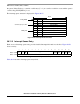
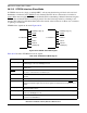
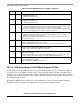
UTOPIA master signals are shown in Figure 30-57.
Figure 30-57. UTOPIA Master Mode Signals
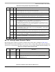
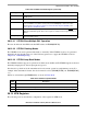
Table 30-44 describes UTOPIA master mode signals.
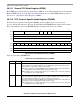
0x0A INT_ICNT Half
Word
Interrupt initial count. User-defined global interrupt threshold—the number of
interrupts required before the CP issues a global interrupt (FCCE[GINT
x
]).
0x0C INTQ_ENTRY Word Interrupt queue entry. Must be initialized to the entry pointed to by INTQ_PTR,
which is initially the first empty entry of the queue. Note that after an overrun
occurs, this entry must be reset to the entry pointed to by INTQ_PTR to reenable
interrupt processing.
1
Offset from INTT_BASE+RCT/TCT[INTQ] × 16
Table 30-44. UTOPIA Master Mode Signal Descriptions
Signal Description
TxDATA[15–0]/[7–0] Carries transmit data from the ATM controller to a PHY device. TxDATA[15]/[7] is the msb when
using UTOPIA 16/8, TxDATA[0] is the lsb.
TxSOC Transmit start of cell. Asserted by the ATM controller when the first byte of a cell is sent on
TxDATA lines.
TxENB
Transmit enable. Asserted by the ATM controller when valid data is placed on the TxDATA lines.
Table 30-43. Interrupt Queue Parameter Table (continued)
Offset
1
Name Width Description
TXDATA[15–0]/[7–0]
TxSOC
TXENB
TXPRTY
TXCLK
TXCLAV[3–0]/TxClav
TXADD[4–0]
PowerQUICC II
RXDATA[15–0]/[7–0]
RXSOC
RXENB
RXPRTY
RXCLK
RXCLAV[3–0]/RxClav
RXADD[4–0]
PowerQUICC II