
User manual

ATM AAL1 Circuit Emulation Service
MPC8260 PowerQUICC II Family Reference Manual, Rev. 2
Freescale Semiconductor 31-11
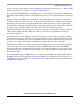
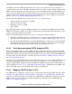
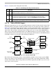
Figure 31-8. Internal CAS Block Formats
31.4.7 Mapping VC Signaling to CAS Blocks
Each ATM channel is connected to a specific CAS block. The ATM controller implements CAS routing
tables (CRT) to maintain the routing of the signaling information from the AAL1 cells to the internal CAS
blocks for receiving, and vice versa for transmitting. Each ATM channel is connected to one receive or
transmit routing table. A CRT resides in a 32-byte space with each entry pointing to one signaling nibble.
To allow maximum flexibility with external framers, the signaling nibble can occupy the first or second
nibble in the internal CAS block (depicted in Figure 31-8).
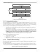
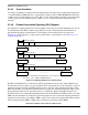
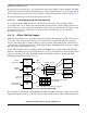
The CRT entries should be initialized only once before the ATM channel is enabled (receiver or
transmitter). The number of entries that should be initialized must be equal to the number of active slots
(channels) in the corresponding MCC super channel. Each super channel is mapped to a unique ATM
connection (VC). The CRT entries are in ascending order based on the channel slots assigned for the MCC
super channel (depicted in Figure 31-9).
XXXX
XXXX
XXXX
XXXX
XXXX
XXXX
XXXX
XXXX
XXXX
XXXX
XXXX ABCD
•
•
•
0 XXXX
ABCD
ABCD
ABCD
1
31
E1 CAS block (32 bytes)
ABCD
•
•
•
0
ABCD
ABCD
ABCD
1
23
T1 – ESF CAS block (24 bytes)
ABA’B’
•
•
•
0
ABA’B’
ABA’B’
ABA’B’
1
23
T1 – SF CAS block (24 bytes)
XXXX
ABCD
ABCD ABCD
12
CAS block resides in the internal RAM.
To allow maximum flexibility in working
with external framers, the signaling nibble
can occupy the first or second nibble in
the CAS entry.
•
•
•
•
•
•
•
•
•
•
•
•
CAS block per trunk