
User manual

ATM AAL1 Circuit Emulation Service
MPC8260 PowerQUICC II Family Reference Manual, Rev. 2
31-12 Freescale Semiconductor
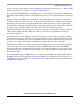
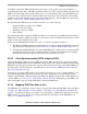
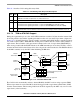
Figure 31-9. Mapping CAS Entry
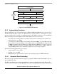
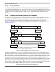
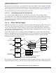
31.4.7.1 CAS Routing Table
Figure 31-10 shows the structure of a CAS routing table. The CP maintains a pointer which steps through
the table and wraps back to the beginning of the table after servicing the last entry (W=1).
Figure 31-10. AAL1 CES CAS Routing Table (CRT)
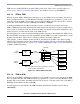
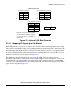
Figure 31-11 describes the structure of a CAS routing table entry.
Figure 31-11. AAL1 CES CAS Routing Table Entry
0123 7
Offset + 0x00 W — F/S Signaling offset pointer (SOP)
0
0
0
0
0
0
0
0
0
XXXX
0
1
ABCD
F/S=0
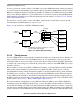
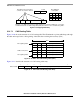
Example of one MCC super channel in ESF framing (T1) containing 4 TDM slots connected to
an ATM channel with one CAS routing table (CRT). See Section 1.4.7.1, “CAS Routing Table.”
One ATM CAS
0
0
1
2
23
Slot 0
Slot 1 Slot 2 Slot 23• • • • • •
routing table
One MCC super channel that
contains only 4 active channels
W=0 Signaling offset pointerFirst signaling nibble — F/S
Last signaling nibble
ATM current pointer
Byte
W=0 Signaling offset pointer— F/S
W=0 Signaling offset pointer— F/S
W=0 Signaling offset pointer— F/S
W=0 Signaling offset pointer— F/S
W=1 Signaling offset pointer— F/S