
User manual

ATM AAL1 Circuit Emulation Service
MPC8260 PowerQUICC II Family Reference Manual, Rev. 2
31-28 Freescale Semiconductor
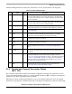
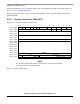
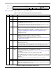
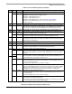
31.9.1.1 AAL1 CES Protocol-Specific RCT
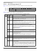
Figure 31-22 shows the AAL1 CES protocol-specific area of an RCT entry.
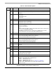
0x04 — RxDBPTR Receive data buffer pointer. Holds real address of current position in the Rx buffer.
0x08 — Cell Time
Stamp
Used for reassembly time-out. Whenever a cell is received, the PowerQUICC II time
stamp timer is sampled and written to this field. See Section 14.3.8, “RISC
Time-Stamp Control Register (RTSCR).”
0x0C — RBD_Offset RxBD offset from RBD_BASE. Points to the channel’s current BD. User-initialized to 0;
updated by the CP.
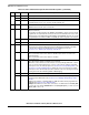
0x0E-0
x18
— Protocol-specific area.
0x1A — MRBLR Maximum receive buffer length. Used in both static and dynamic buffer allocation.
Note that in CES mode (CESM=1) this value must be a multiple of 8 (MCC limited).
0x1C 0–1 — Reserved, should be cleared during initialization.
2–7 PMT Performance monitoring table. Points to one of the available 64 performance
monitoring tables. The starting address of the table is PMT_BASE+PMT × 32. Can be
changed on-the-fly.
8–15 RBD_BASE RxBD base. Points to the first BD in the channel’s RxBD table. The 8 most-significant
bits of the address are taken from BD_BASE_EXT in the parameter RAM. The four
least-significant bits of the address are taken as zeros.
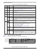
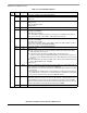
0x1E 0–11
12 CCASM Core CAS modify. When this mode is enabled, the CP sets OCASSR[MCASB
n
] sticky
bit each time the outgoing (ATM to TDM) CAS block is changed.
0 Core CAS modify mode is disabled.
1 Core CAS modify mode is enabled.
See Section 31.10, “Outgoing CAS Status Register (OCASSR).”
13 CESM Circuit Emulation Service Mode.
0 CES operation mode is disable. Adaptive Slip control mechanism is disabled.
1 CES operation mode is enable. Adaptive Slip control mechanism is enabled.
14 — Reserved, should be cleared during initialization.
15 PM Performance monitoring. Can be changed on-the-fly.
0 No performance monitoring for this VC.
1 Perform performance monitoring for this VC. Whenever a cell is received for this VC
the performance monitoring table that its code is written in the PMT field is updated.
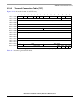
0 1 2 3 4 5 6 7 8 9 10 11 12 13 14 15
Offset + 0x0E SRTS_DEV — PFM SRT INVE STF —
Offset + 0x10
OCASB/SRTS_TMP — —
Valid Octet Size (VOS)
Offset + 0x12
SPV — Structured Pointer (SP)
Offset + 0x14
RBDCNT
Figure 31-22. AAL1 CES Protocol-Specific RCT
Table 31-5. RCT Field Descriptions (continued)
Offset Bits Name Description